ESP32 weather station 2.0: wireless sensors, Open-Meteo API, IPS display, mmWave radar, particulate matter sensor and much more
The ESP32 weather station is now over a year old. So it's high time for an update. I have therefore spent the last few weeks developing a completely improved version of the weather station. The changes affect both the software and the hardware and include the following points:
- New display with IPS panel
- Change from Arduino Framework to ESP-IDF
- Setup screen for setting the time zone, Wi-Fi, location and other values
- Free Open-Meteo API instead of OpenWeather API
- 24GHz mmWave radar for human presence detection
- Improved light sensor with I2C interface
- More stable housing with melt-in thread
Of course, the complete structure is once again open source and is linked in the appropriate places.
The list of features has become a little longer as a result:
- Base station with ESP32-S3 and 7-inch IPS display.
- Setup screen for configuring the weather station.
- Wireless sensors based on ESP32. There are three possible sensor variants.
- Battery of the wireless sensors is charged via solar cells.
- Very low power consumption of the wireless sensors thanks to deep-sleep mode and ESP-NOW protocol.
- Depending on the wireless sensor, 4 or 8 sensors can be configured using a DIP switch.
- Wireless sensors connect to the base station fully automatically.
- Each wireless sensor measures temperature, humidity and air pressure.
- The base station provides temperature, humidity, VOC index, particulate matter, NOx and CO2 content.
- Detailed weather forecast via the Open-Meteo API for the next 48 hours or 7 days.
- The display automatically adjusts to the brightness of the surroundings.
- If nobody is near the weather station, the display is automatically dimmed.
- Housing from the 3D printer, so that the weather station is also suitable for the living room.
In the rest of this article, I will take a closer look at the individual hardware and software components. For unchanged parts, please refer to the description of the previous version.
Structure of the weather station
The functionality of the weather station has hardly changed. Only the photo resistor, which was connected to an A/D converter of the ESP32, has been replaced by a BH1750 light sensor. In addition, a radar sensor for detecting human presence is connected to the I2C bus. This means that five devices in the weather station are connected to the microcontroller via the I2C bus.
Data is transmitted from the wireless modules via the energy-saving ESP-NOW protocol. Each wireless module is assigned its own number via a DIP switch for clear identification. The power supply is provided by a 18650 lithium-ion battery, which is charged using 6-volt solar cells. The weather data is retrieved periodically using a free API via Wi-Fi. I currently use the Open-Meteo API for this, but in principle any other API is also possible.
Software architecture of the weather station
In my article about the MaTouch display, I also describe the display driver that I wrote for this display (and other parallel displays). For this driver, however, I did not use the Arduino framework, but the ESP-IDF framework. The reason was that I wanted to use the latest features for driving parallel displays from the Espressif API. For this reason, I also rewrote the rest of the software. This is basically not a problem, as the Arduino framework ultimately only accesses functions of the ESP-IDF framework. However, I also had to write a corresponding driver for the mmWave radar module and the light sensor, as there are only Arduino libraries for these. The following diagram shows the structure of the software:
The layout of the LVGL screens was again largely created with SquareLine Studio. A little trick makes it possible to use more than 150 widgets. However, this is a bit cumbersome and you should have a good XML editor. The source code of the weather station is again available on GitHub.
Setup screen for setting all variable values
The setup screen actually already exists in the old version. However, it was only added later, so I will describe it briefly here. The following image provides an overview of all settings:
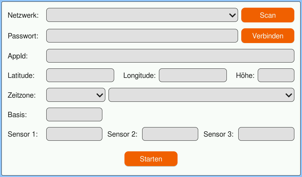
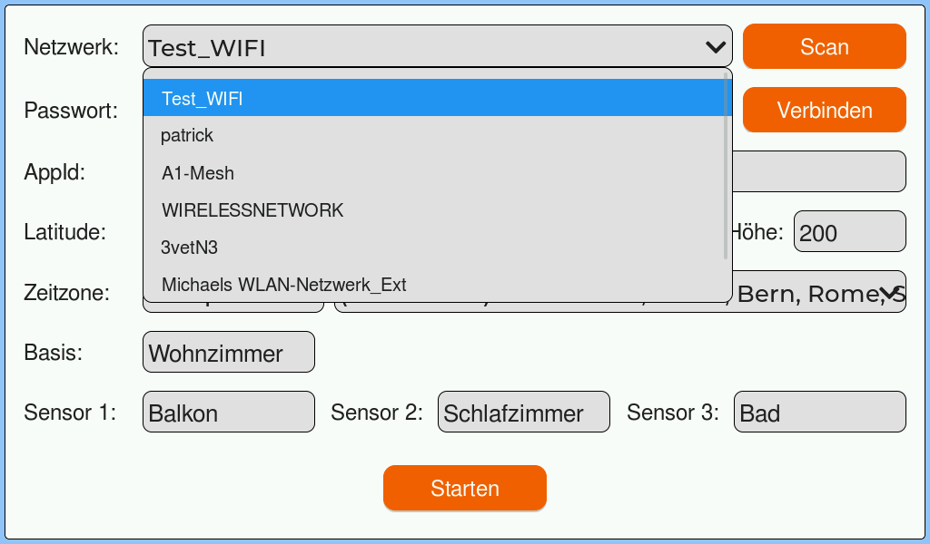
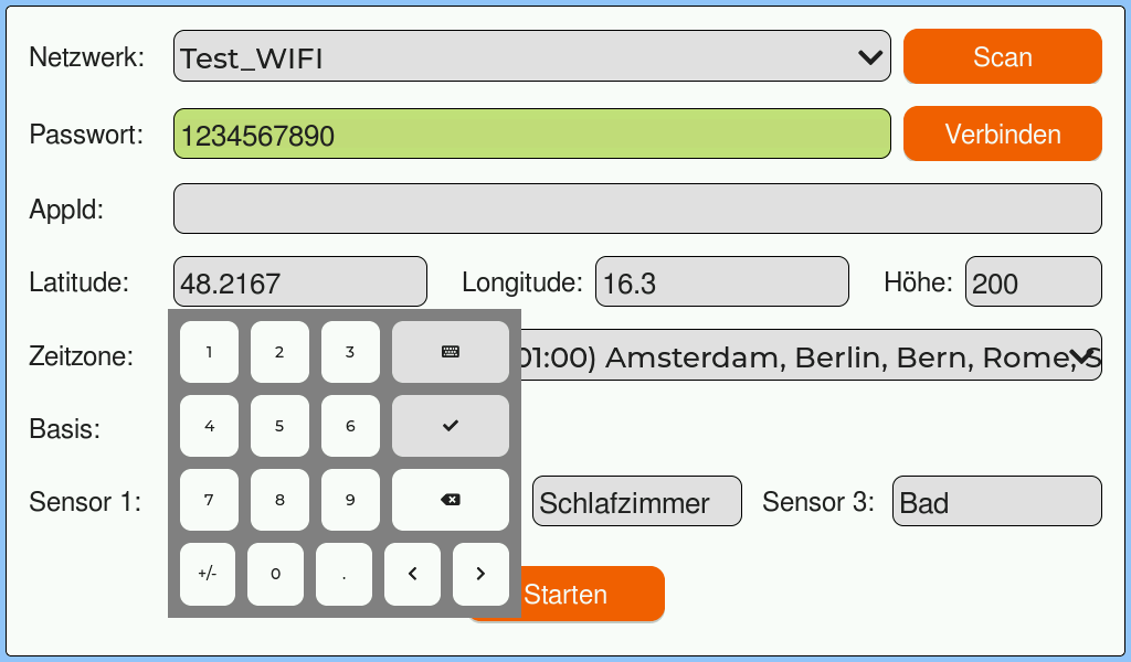
Firstly, the Wi-Fi access can be configured. The scan button searches for the available networks. You can then select your own network from the drop-down list. Once you have entered the corresponding password, you can use the Connect button to check whether a connection can be established.
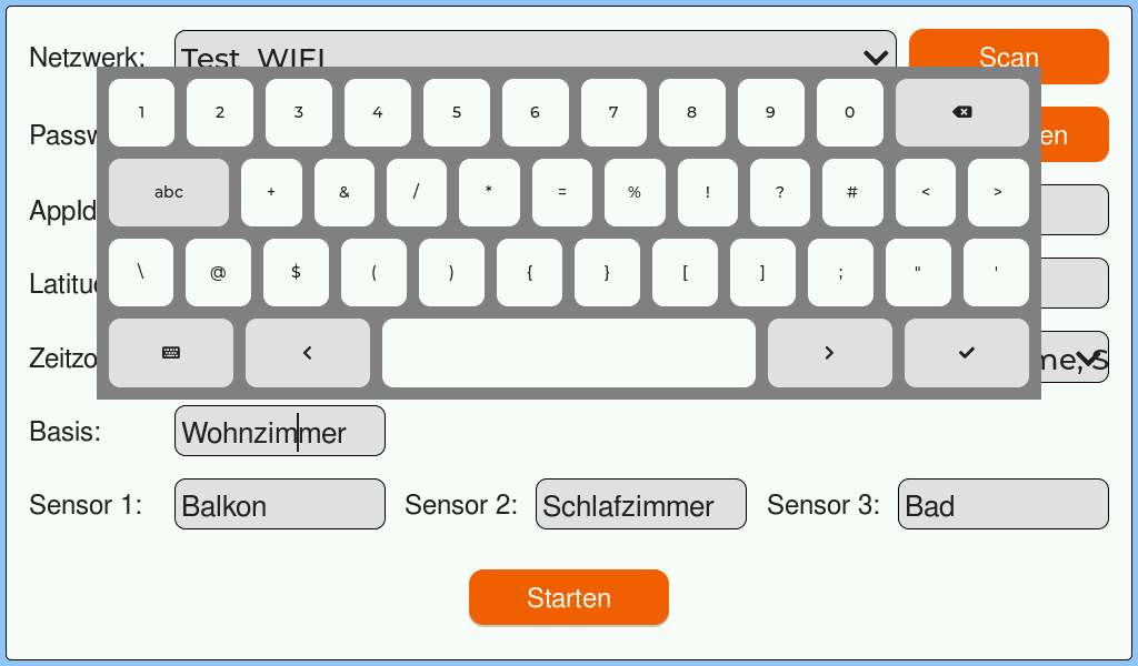
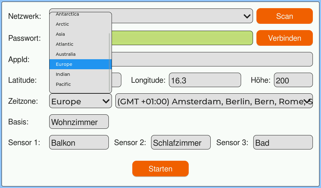
AppId is no longer actually required. The ID of OpenWeatherMap was entered here. However, the new weather API no longer requires this. Nevertheless, I will keep the setting for the time being. Maybe I will add OpenWeatherMap, then you can control which API should be used.
The time zone is important for displaying the time. It also controls daylight saving time. The last fields are the labels of the respective sensors or the weather station itself. Finally, click on Start to switch to the screen with the weather and sensor data.
The weather station display
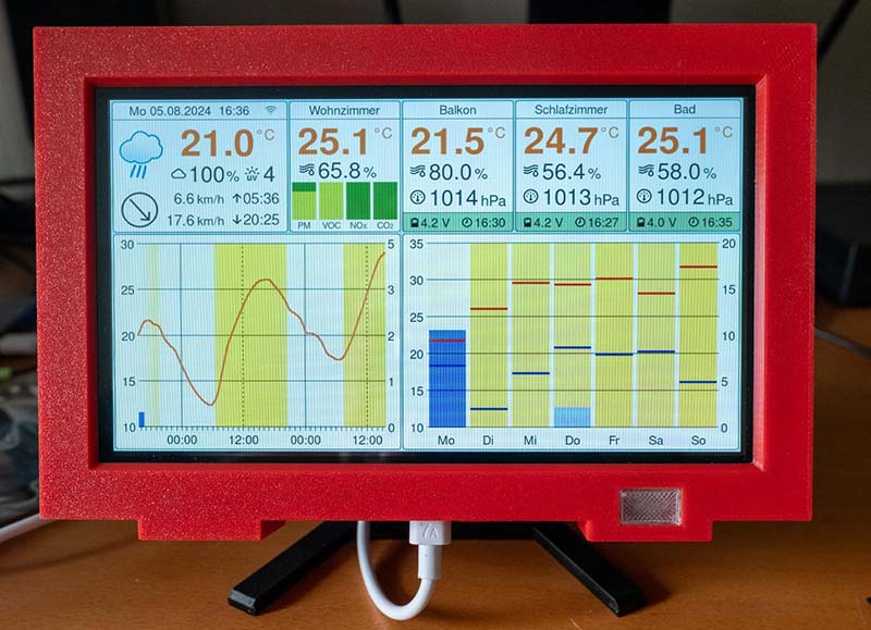
My aim was to show as much information as possible on the small display while still maintaining a clear layout. I hope that I have succeeded in doing this. The following image shows all the information shown on the display. This is purely test data, so don't be surprised at the values.
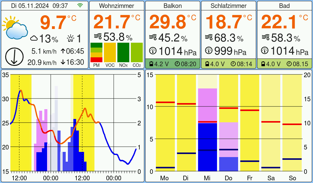
The top left and the two diagrams are the data from the weather API. Current values, an hourly forecast for 48 hours and a daily forecast for 7 days are displayed here. At the top next to the current values is the data from the base station and next to it the values from the sensors. The following diagrams show the areas again with the data labelled.
Current weather and sensor data
Base station data
The SEN55 can measure four different particle sizes, which is why the left-hand bar is divided into four smaller bars. The bottom bar corresponds to PM1 and PM10 is at the top.
Forecast for the next 48 hours
The temperature curve shows the dew point in colour. The dew point is the temperature at which the air is saturated and water vapour begins to condense.
- The dew point plays a decisive role with regard to the sensation of temperature, especially in humid conditions: High dew point (above 18°C): The air contains a lot of moisture and sweat evaporates more poorly. This makes the temperature feel much warmer and uncomfortably humid. From around 21°C it becomes oppressive and stressful for many people.
- Low dew point (below 13°C): The air is drier, sweat can evaporate easily and it feels more comfortable, even at high temperatures.
Of course, these values are very subjective and correspond more to my personal temperature perception.
Forecast for the next 7 days
The temperature scale adapts dynamically to the highest and lowest values. The amount of precipitation, on the other hand, is displayed on a fixed scale so that you can see at a glance whether it is raining a lot or a little. For the hourly forecast, I have set the maximum value to 5 mm, while for the daily forecast it is 20 mm, as it rarely rains or snows more than that. In future, I could possibly make these values configurable in the setup.
Free Open-Meteo API instead of OpenWeather API
One of the most fundamental changes to the weather station is the weather API. Creating an API key with OpenWeatherMap is quite cumbersome and I didn't like the idea of depositing a credit card either. Unfortunately, there is no option without a credit card, so access is simply blocked if the daily limit is exceeded. You can select a limit in the settings, but that doesn't change the fact that you have to enter a credit card..
In one of the comments to a previous article, someone suggested Open-Meteo. I've now had a look at it and I think the data is pretty good. Open-Meteo is a weather API that offers free use for non-commercial projects with up to 10,000 API calls per day. The API provides hourly weather forecasts for 7 days and can be extended up to 16 days. It uses data from various national weather providers to provide the best possible forecast for any location worldwide. The API is quite simple and is well described on the Open-Meteo website.
For example, calling the weather API via HTTPS for the current weather looks like this:
static const char *WEATHER_URL_BASE = "https://api.open-meteo.com/v1/forecast";

static const char *WEATHER_URL_CURRENT =
        "https://api.open-meteo.com/v1/forecast?"
        "latitude=12.34&longitude=56.78&"
        "current=temperature_2m,relative_humidity_2m,apparent_temperature,"
        "is_day,weather_code,cloud_cover,wind_speed_10m,wind_direction_10m,wind_gusts_10m,uv_index&"
        "timeformat=unixtime&timezone=auto";

http_response_t response = {0};

esp_http_client_config_t config = {
	.event_handler = _http_event_handler,
	.url = WEATHER_URL_BASE,
	.crt_bundle_attach = esp_crt_bundle_attach,
	.user_data = &response,
	.disable_auto_redirect = true,
};

esp_http_client_handle_t client = esp_http_client_init(&config);

esp_http_client_set_url(client, WEATHER_URL_CURRENT);

err = esp_http_client_perform(client);
if (err == ESP_OK) {

	cJSON *json = cJSON_Parse(response.buffer);
	if (json == NULL) {
		const char *error_ptr = cJSON_GetErrorPtr();
		if (error_ptr != NULL) {
			ESP_LOGE(TAG, "Error before: %s", error_ptr);
		}
	}
	else {
		cJSON *current = cJSON_GetObjectItem(json, "current");

		current_data.temperature_2m = cJSON_GetObjectItem(current, "temperature_2m")->valuedouble;
		current_data.relative_humidity_2m = cJSON_GetObjectItem(current, "relative_humidity_2m")->valueint;
		current_data.apparent_temperature = cJSON_GetObjectItem(current, "apparent_temperature")->valuedouble;
		current_data.is_day = cJSON_GetObjectItem(current, "is_day")->valueint;
		current_data.weather_code = cJSON_GetObjectItem(current, "weather_code")->valueint;
		current_data.cloud_cover = cJSON_GetObjectItem(current, "cloud_cover")->valueint;
		current_data.wind_speed_10m = cJSON_GetObjectItem(current, "wind_speed_10m")->valuedouble;
		current_data.wind_direction_10m = cJSON_GetObjectItem(current, "wind_direction_10m")->valueint;
		current_data.wind_gusts_10m = cJSON_GetObjectItem(current, "wind_gusts_10m")->valuedouble;
		current_data.uv_index = cJSON_GetObjectItem(current, "uv_index")->valuedouble;
	}

	cJSON_Delete(json);

	if (response.buffer) {
		heap_caps_free(response.buffer);
		response.buffer = NULL;
		response.buffer_len = 0;
	}

} else {
	ESP_LOGE(TAG, "HTTP GET request failed: %s", esp_err_to_name(err));
}

esp_http_client_close(client);
I use cJSON to parse the JSON data provided by the weather API. The library is written in C and is very suitable for this task. With its help, I can extract the weather information received in a structured way and prepare it for display on the weather station's screen.
Display with IPS panel
The actual motivation for the new version of the weather station was the display from Makerfabs. I was sent the display in February and after some initial disappointment with the 800x600 pixel version, I was even more excited about the 1024x600 pixel version. Details can be found in my article about the MaTouch displays from Makerfabs. I have not yet found another 7 inch display with ESP32-S3 and IPS panel. Of course, this display is not perfect either. The few pins for the peripherals and the exotic connectors are particularly annoying. This is also one of the reasons why I now use a light sensor with an I2C interface instead of a photo resistor. Every display I have looked at so far has this bus.
I solved the problem with the plugs and the missing connection for the 5 volt power supply pragmatically and simply soldered the cables directly to the board:
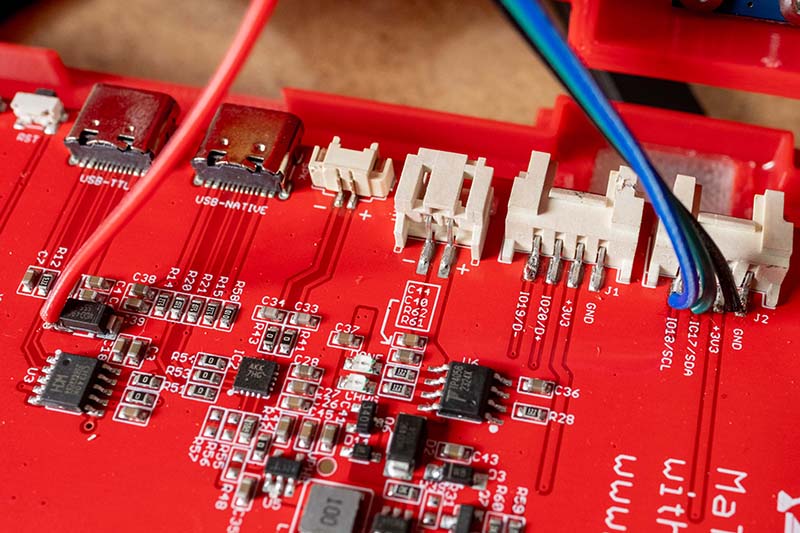
I soldered the 5 volts to the Schottky diode on the side that is connected to the USB plug, i.e. the anode. Here you really have 5 volts available. In the circuit diagram from Makerfabs you can see a solder pad, but this is connected to the cathode of the Schottky diode. Even the labelling says 5 volts. But in reality, only 4.4 volts are present here, as a certain voltage drops across the diode. This can also be read in the data sheet of the diode (type SS54), where a (maximum) value of 0.55 volts is specified.
The environmental sensors used
The selection of suitable sensors was a challenge for the weather station. Many inexpensive models provide inaccurate values, and developing your own drivers is time-consuming. The choice therefore fell on sensors from Bosch Sensortec and Sensirion, which offer both precise measurements and good ESP32 support. A detailed description of the sensors can be found in the first version of the weather station, so here is just a brief summary.
Bosch Sensortec BME280
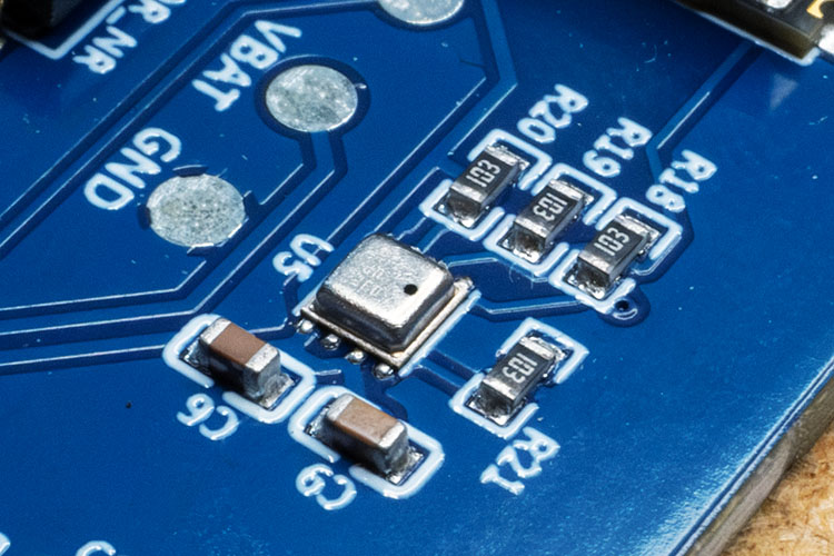
The SEN55 measures particulate matter (PM1-PM10), volatile organic compounds (VOCs), nitrogen oxides (NOx), temperature and humidity. The particle sensor works with laser technology and enables precise air quality monitoring. The wide measuring range for fine dust particles makes it particularly versatile. Communication takes place via I2C.
Sensirion SEN55
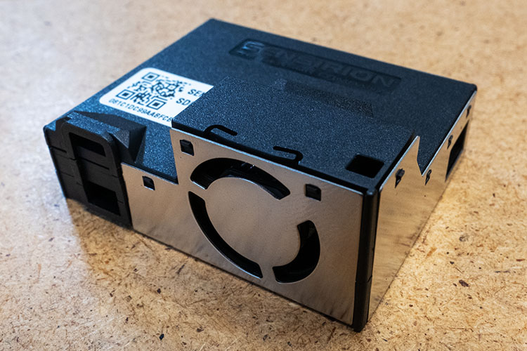
The SEN55 measures particulate matter (PM1-PM10), volatile organic compounds (VOCs), nitrogen oxides (NOx), temperature and humidity. The particle sensor works with laser technology and enables precise air quality monitoring. The wide measuring range for fine dust particles makes it particularly versatile. Communication takes place via I2C.
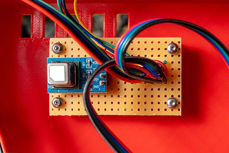
Sensirion SCD41
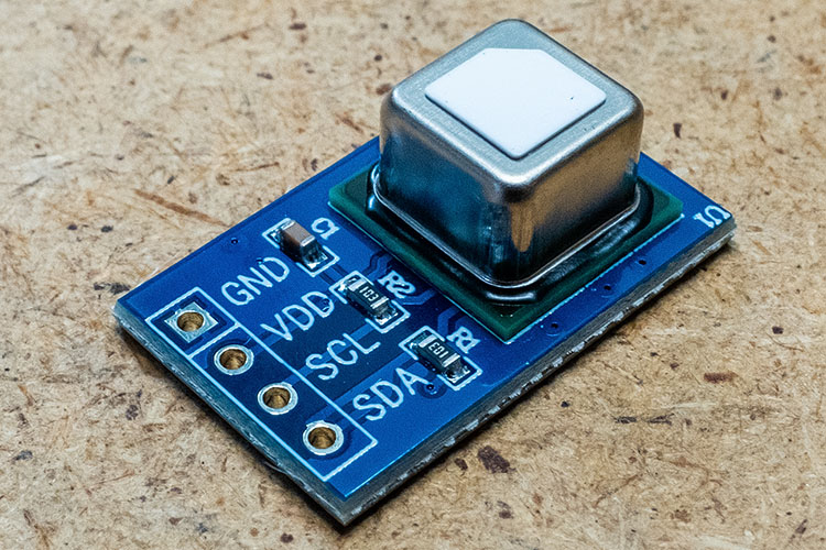
The SCD41 measures the CO₂ concentration using NDIR technology, which is based on the absorption of infrared light. As temperature and humidity can influence the measurement accuracy, corresponding sensors are integrated for compensation. This sensor is also addressed via I2C.
24GHz mmWave radar human presence sensor
In addition to the display, the housing of the weather station also contains the environmental sensors from Sensirion. Of the two sensors, I use the particulate matter sensor to measure the current temperature. However, the display heats up a little over time, which of course distorts the measured value. Sensirion has also provided the option of a correction factor, which you have to adjust to your respective device. I have determined this value more or less accurately by experiment, but even this is not completely accurate. The display adjusts its brightness to the surroundings and consequently also becomes more or less warm.
With the new display, I even have the feeling that it heats up even more. That's why I was looking for another solution. Wouldn't it be much better if the display only lit up at full brightness when someone was actually looking at it? Otherwise, the display could either be switched off completely or at least light up at the lowest brightness. The heating during this short time would be completely negligible. During my research, I came across the mmWave radar sensor from DFROBOT. This sensor can be used to determine whether someone is in front of the sensor and at what distance. This makes it possible for the display to only assume its normal brightness when someone is less than three metres away from the display, for example.
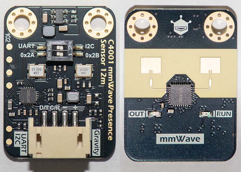
I think this sensor is so exciting that I will probably write a separate article about it. Unfortunately, DFROBOT's documentation is very sparse and it was only after several requests that I was sent some more documents. But even now, not all the functions are completely clear to me.
Light sensor with I2C interface
Until now, the brightness of the display was controlled via a photo resistor. However, two things bothered me about this solution. Firstly, it is difficult to always get the same type. The parameters of the brightness control have to be adapted to the respective type. Secondly, I am not very satisfied with the A/D converter of the ESP32. The values are very scattered, which has to be compensated for by software, otherwise the brightness of the display would constantly fluctuate. That's why I was looking for a standardised light sensor that can be controlled via the I2C interface. The BH1750 fulfils exactly this requirement.
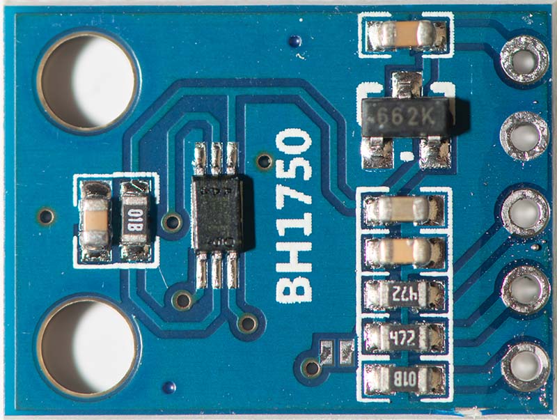
The BH1750 is a digital ambient light sensor that is ideal for recording ambient light values to adjust a backlight. It has an I2C interface, a large detection range (1 - 65535 lux) and a sufficiently high resolution. Above all, this small circuit board is widely available and costs only a few euros.
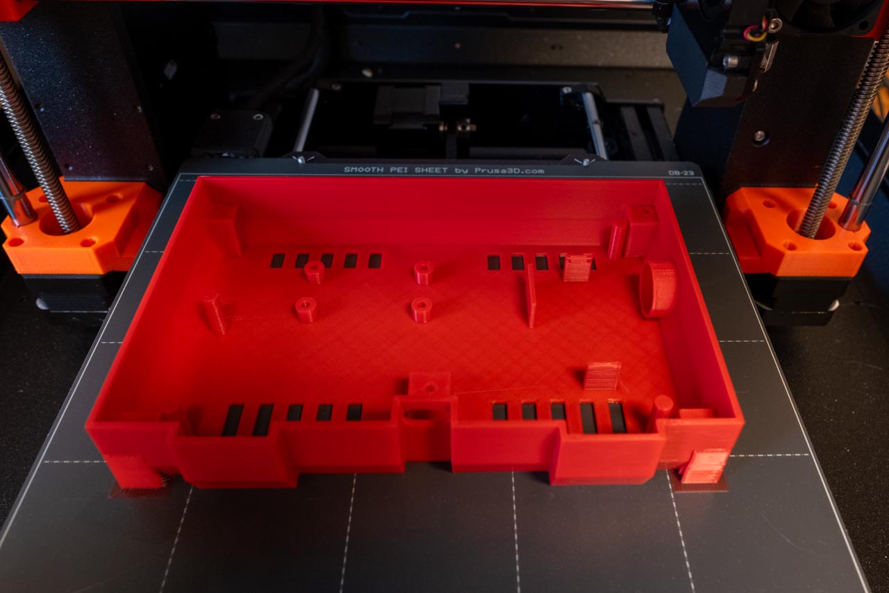
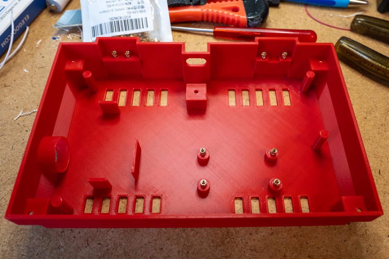
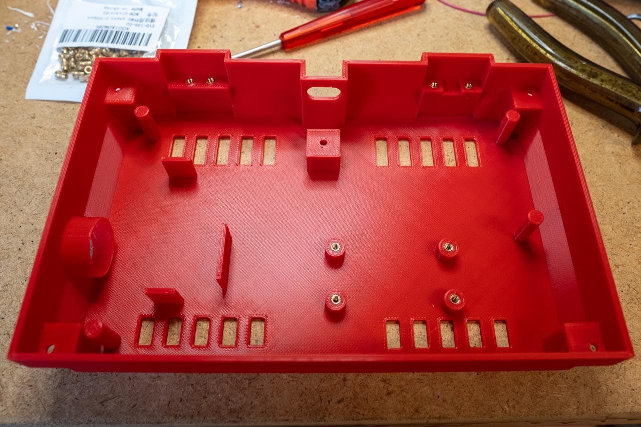
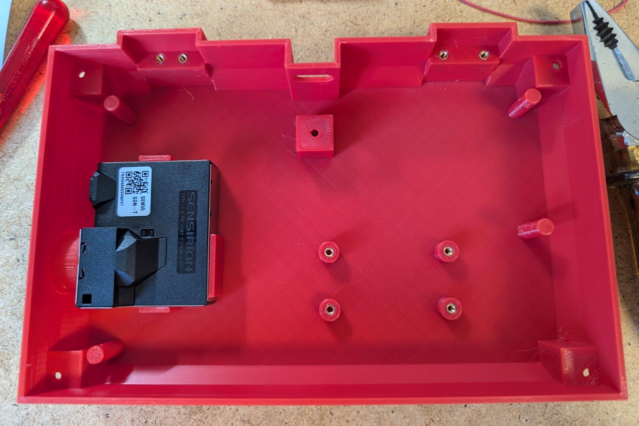
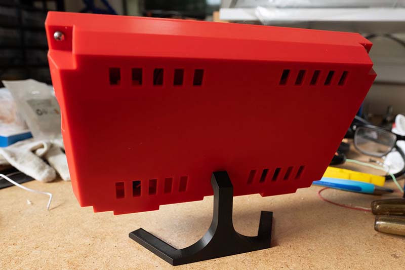
More stable case with threaded inserts for melting in
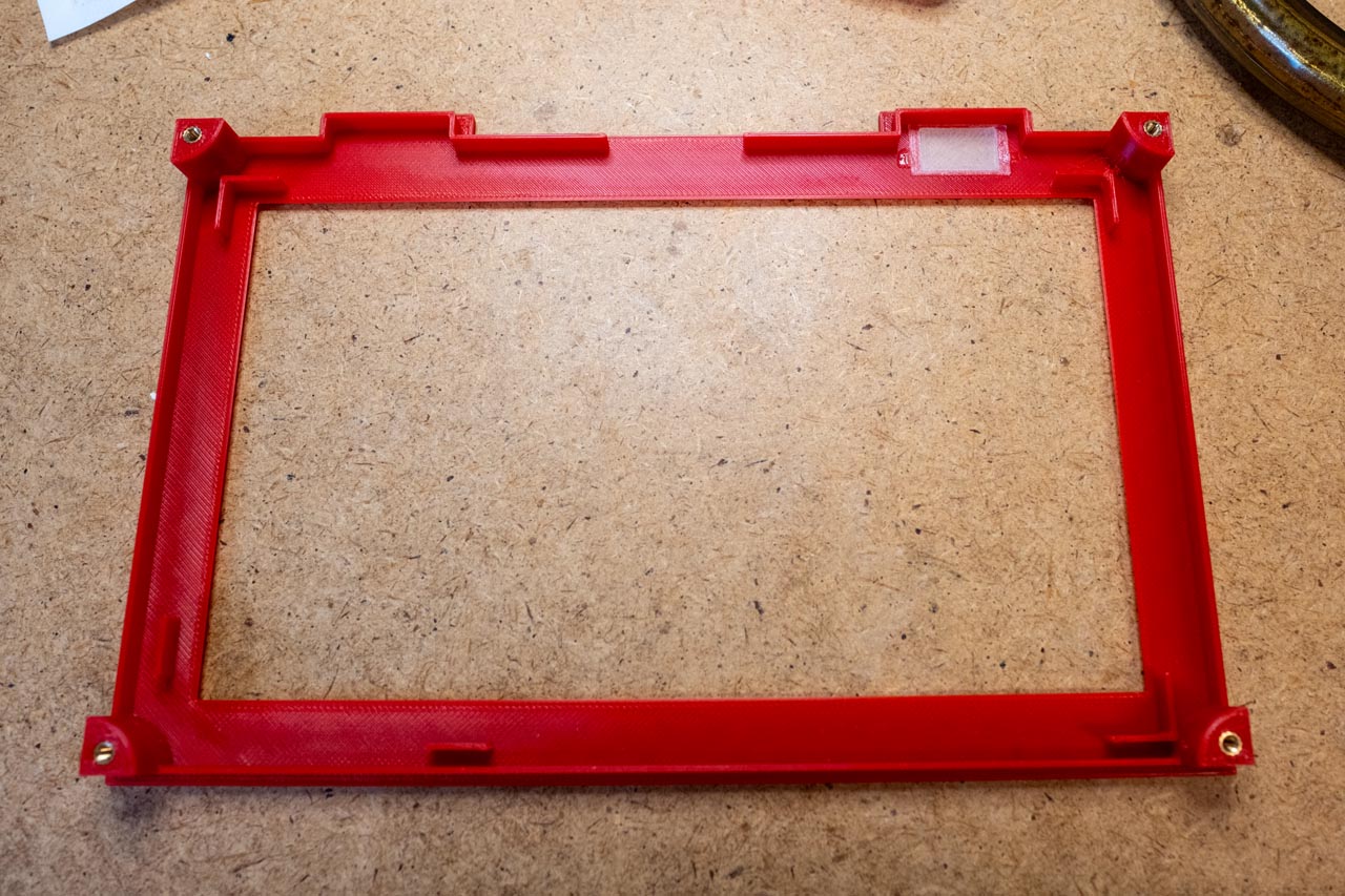
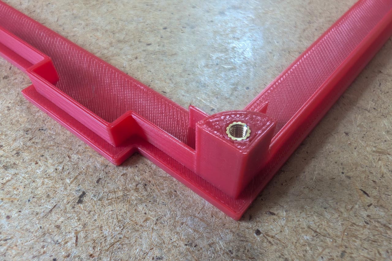
Unfortunately, the Makerfabs display looks completely different to the Sunton display. I therefore had to design a new housing. For the first time, I used threaded inserts for melting. Until recently, I didn't even know that such a thing existed, so I was nervous about melting them down. After hours of 3D printing, it would be a shame if I ruined the parts again. But it turned out to be child's play, even the drill holes near the wall were no problem. Here are a few photos of the housing and the assembly. Unfortunately I made a small mistake. Anyone notice it?
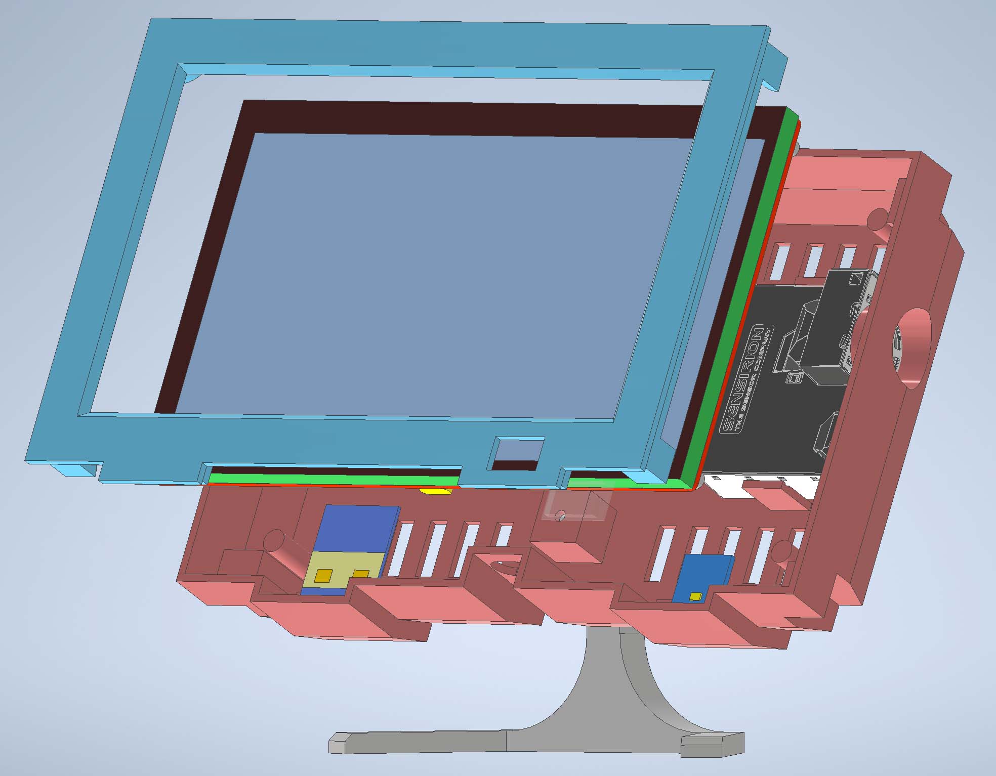
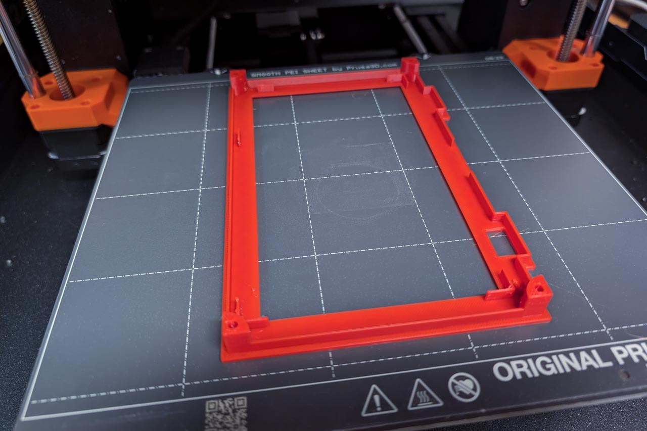
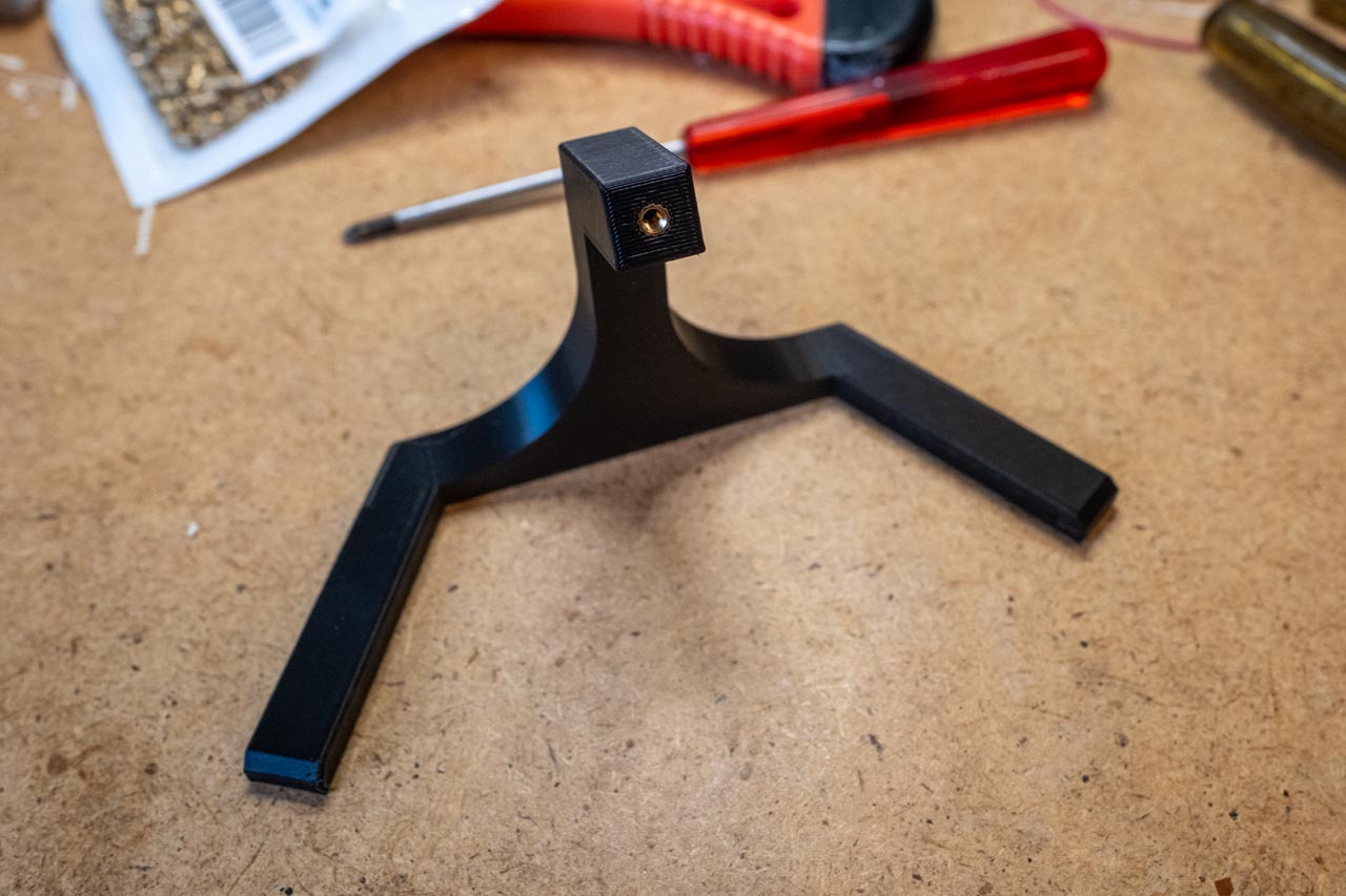
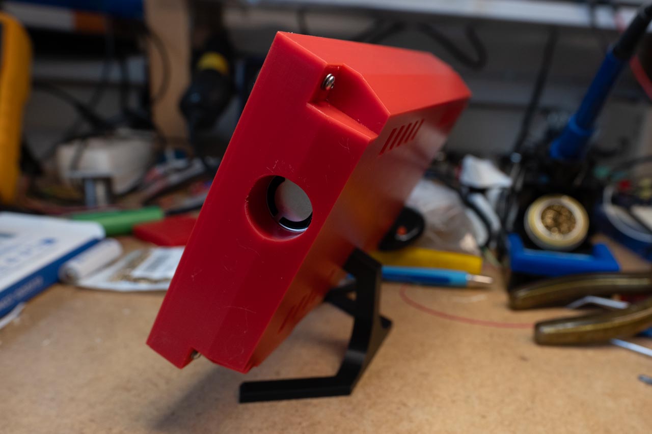
I'm particularly proud of the stand. Isn't it incredibly elegant? :-)
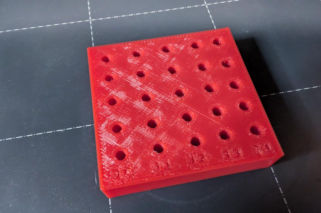
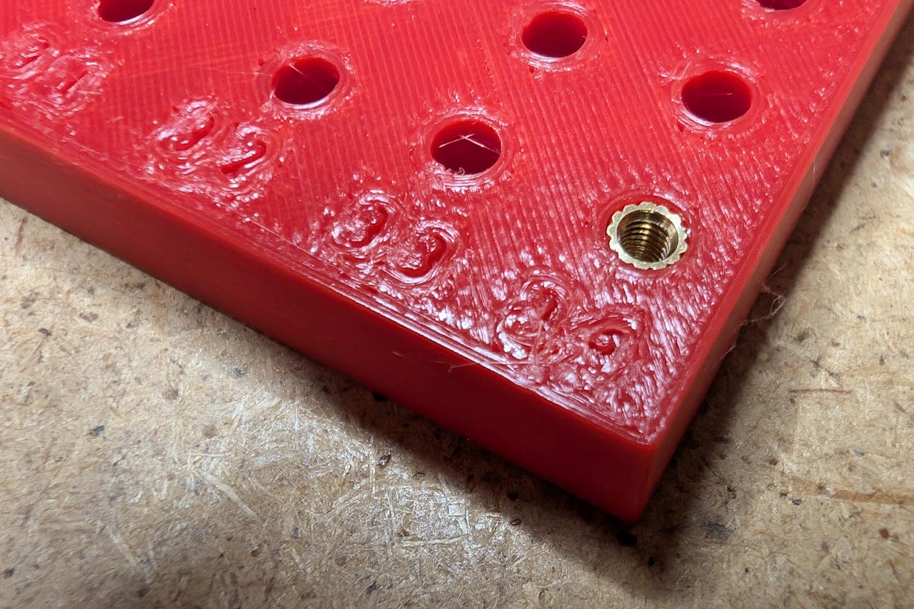
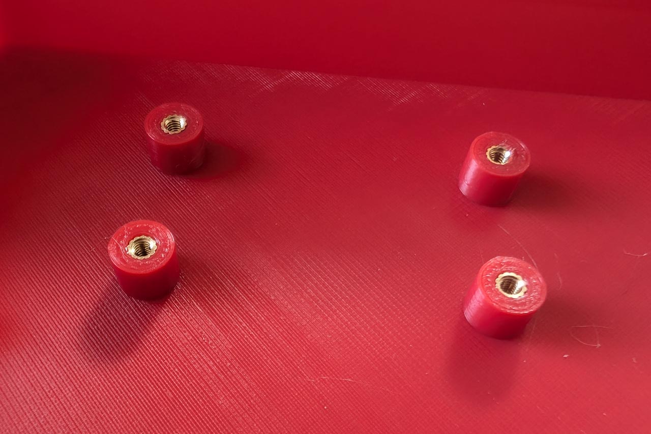
The threaded inserts are of the M2.5x5x3.5mm type. To find the right diameter for the holes, I first printed a test block with different diameters. The ideal value for the threaded inserts turned out to be 3.4 mm.
When designing the housing, I usually allowed for about 0.5 mm of air, but it turned out that the Prusa printer is so precise that the parts then wobble. This was particularly the case with the foot. So I used the exact values again and the foot actually fits perfectly in the housing.
The STEP and STL files of the parts for self-printing are available on GitHub.
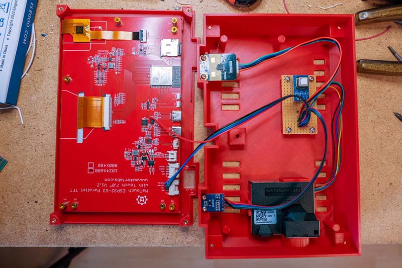
Assembling the weather station
The following pictures show the assembly of the weather station. The CO2 sensor and the cables to the other sensors are soldered onto a small strip grid board. Unfortunately, the order of the pins is different for each device, so the cables look a little mixed up...
And this is how the weather station is completely set up. The display is simply placed in the front panel. No screws are required for this. A sheet of transparent filament is placed in the recess for the light sensor. I simply glued this plate in place. Then the base is screwed onto the back from behind.
Finally, carefully place the back onto the front and secure it with the 4 screws. The weather station should then look like this:
The weather station is now fully assembled.
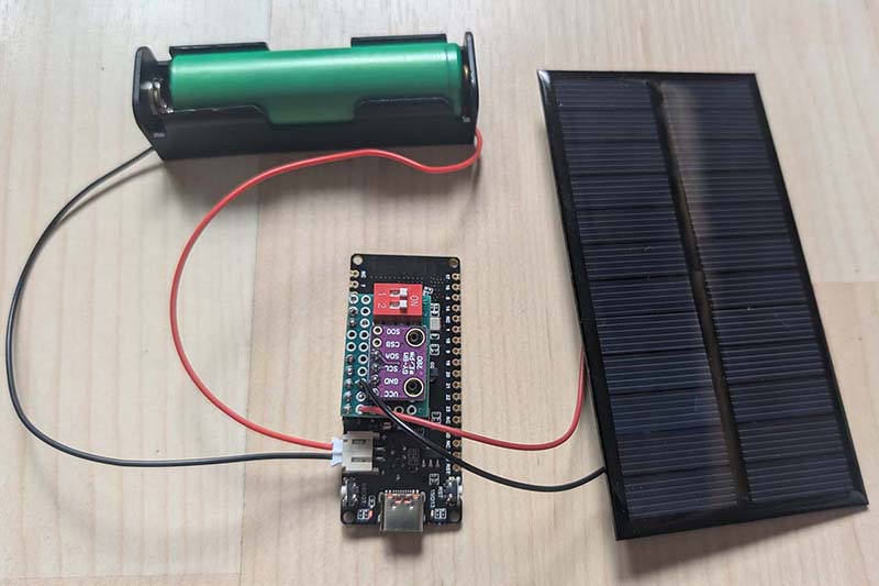
The wireless sensors
There are now three versions of the wireless sensors:
The original sensor for the Raspberry weather station. Here, the ESP32, charge controller and the BME280 are on separate circuit boards:
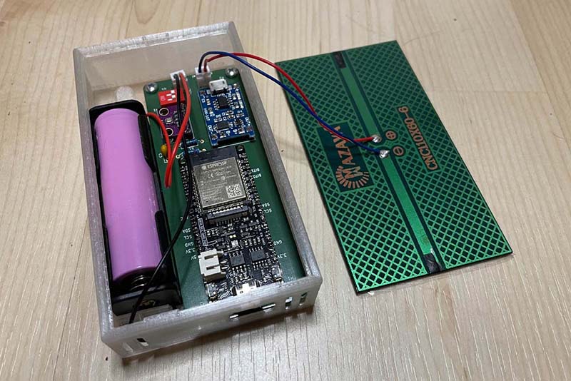
My self-designed circuit board, which contains all the components:
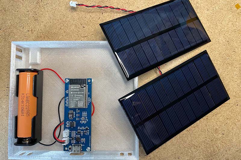
The Version with the FireBeetle 2 ESP32-C6. Here, only the BME280 is a separate board:
All three versions are equally suitable as sensors. The last version is probably the easiest to replicate. The components are easy to obtain and no special PCB is required for assembly. The energy consumption is also approximately the same for all versions.
Conclusion
I would now consider the weather station to be very mature. In the coming weeks, I will mainly be monitoring the quality of the Open-Meteo data. For now, however, the values look quite good. There will certainly still be some fine-tuning of the software.
For the future, I am considering whether a wireless sensor with a small display and the Sensirion environmental sensors would make sense. However, this device would then have to be supplied with power via USB. And for the more distant future, I'm toying with the idea of developing sensors with LoRa wireless technology. I just need a good use case for this, as Wi-FI technology is completely sufficient in a city flat
If you have any questions or other suggestions, just send me a message. I'm always happy to receive feedback!