CrowPanel Advance 7" Display: Basics and GUI Development with LVGL/ESP-IDF
Recently, more and more boards combining an ESP32 directly with a display have been appearing. For us makers, this combination is particularly exciting, as the ESP32 provides a powerful framework on one hand, and the large display opens up many new application possibilities on the other. A few weeks ago, Elecrow introduced a new, very interesting display: the CrowPanel Advance 7” HMI ESP32-S3 AI-Powered IPS Touch Screen from the Advanced Series.
This display presents itself as a versatile platform for Human-Machine Interfaces (HMI) and IoT projects. Equipped with the ESP32-S3 microcontroller, a 7-inch touchscreen, and support for various development environments, this display offers a solid foundation for a wide range of applications. In this post, I'll introduce the display and show you how to get your first program running on it using ESP-IDF..
First, a brief overview of the display's most important features:
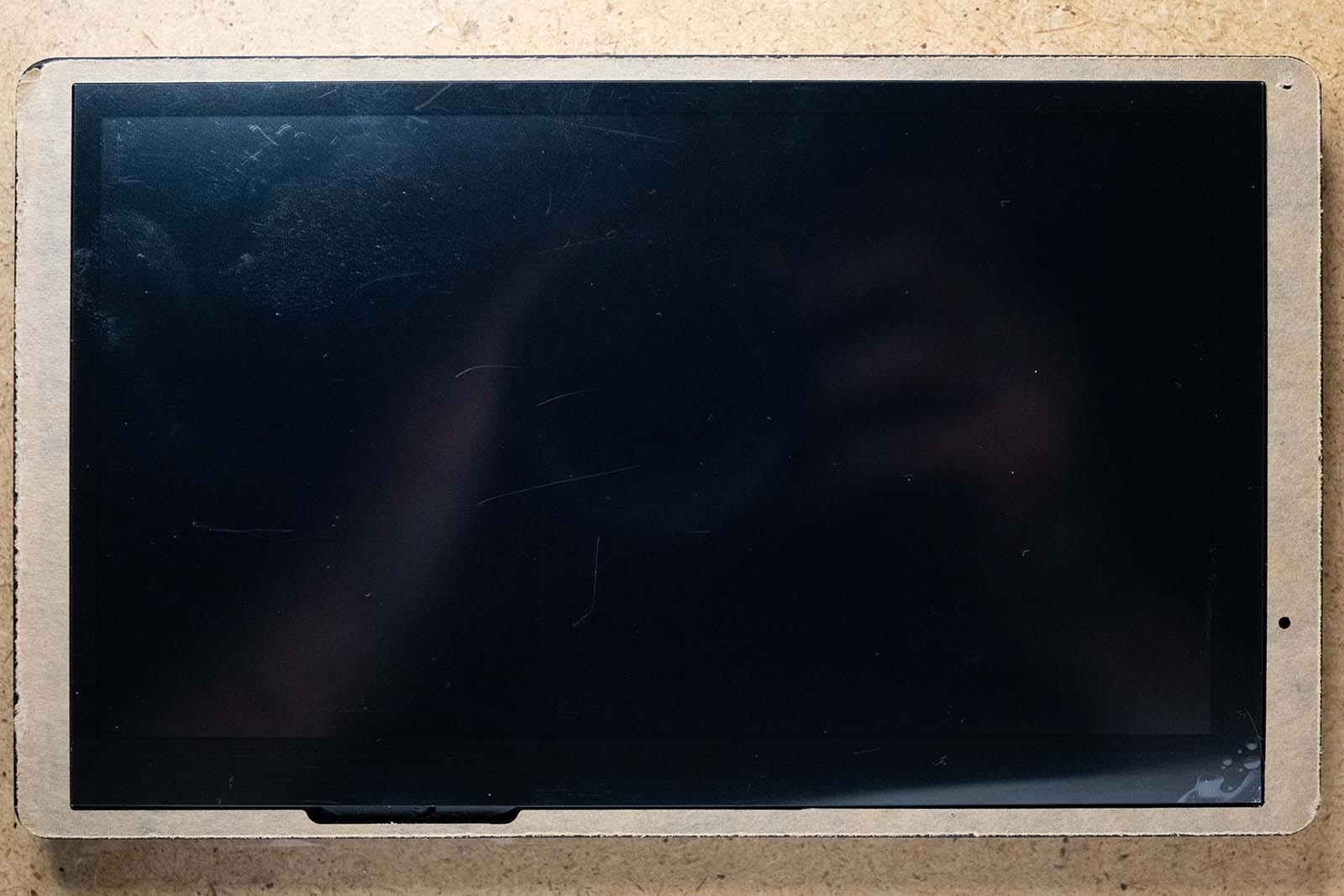
- 7-inch IPS display with a resolution of 800x480 pixels and a brightness of 400 cd/m².
- Capacitive touch control.
- ESP32-S3-WROOM-1-N16R8 module (dual-core 32-bit LX7 microprocessor with up to 240 MHz).
- 512KB SRAM, 8MB PSRAM and 16MB Flash memory.
- 2.4GHz Wi-Fi (802.11 b/g/n) and Bluetooth 5 (LE).
- Real-time clock with battery.
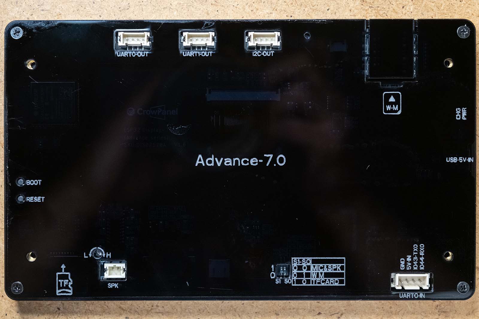
- Peripheral interfaces: 2x UART0, 1x UART1, 1x I2C.
- TF card slot, USB-C connection, speaker connection, battery connection, connection for expansion modules.
- Extended AI functionality (integrated microphone and speaker with class-D amplifier on the board).
- Modular design allows replacement of modules to support different communication protocols (Zigbee, LoRa, nRF2401, Matter, Thread, Wi-Fi 6).
- Development environments: Arduino IDE, Espressif IDF, PlatformIO and MicroPython.
- Compatible with the LVGL graphics library.
Many of these features can also be found on other ESP32-based boards, but some points are, with a few exceptions, unique to this board.
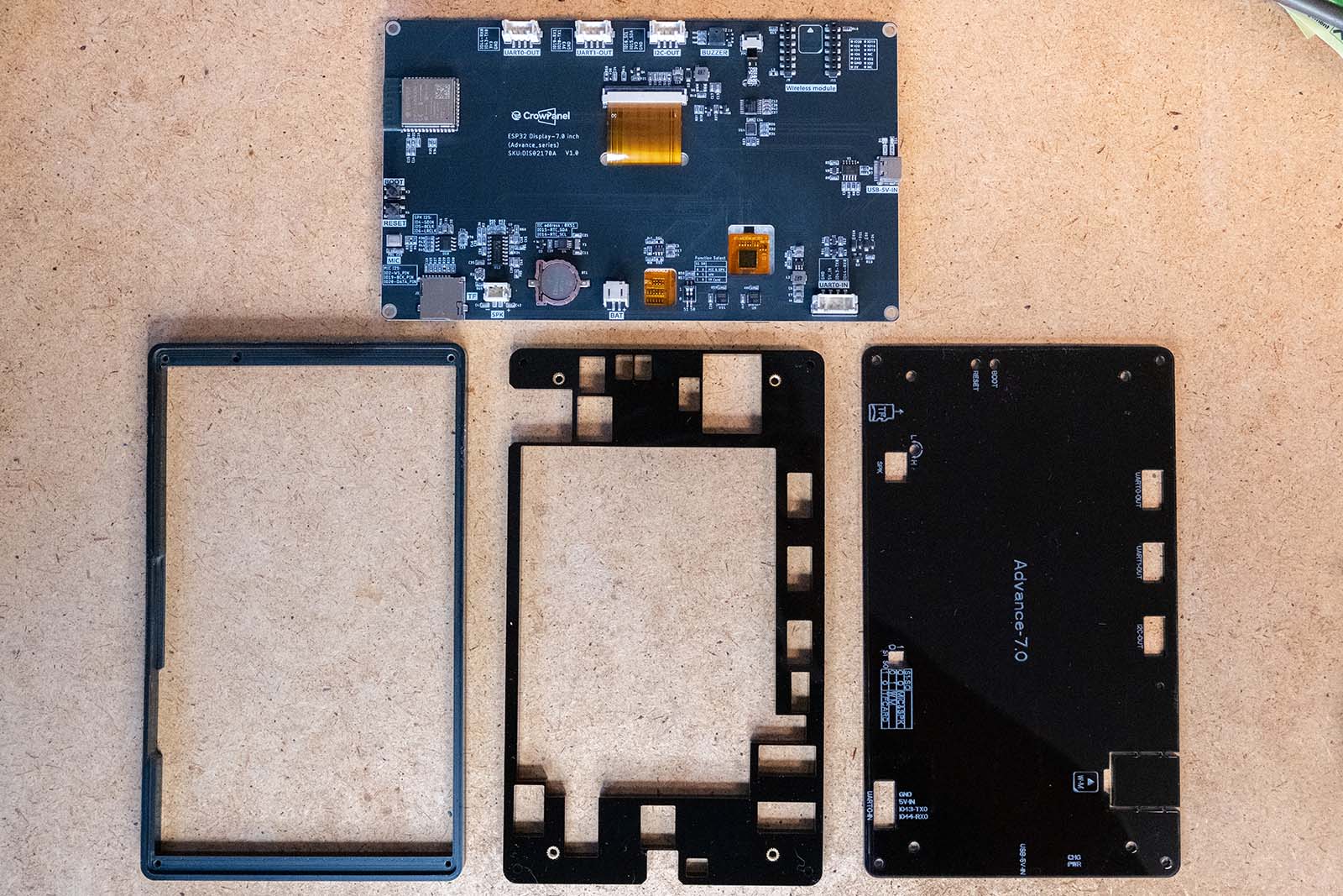
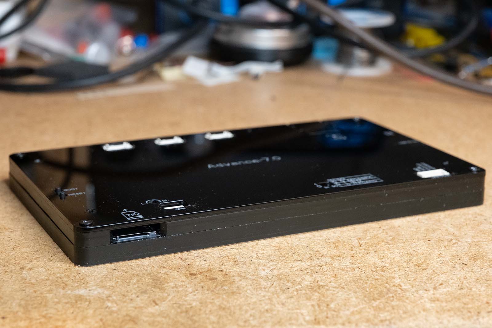
The standard package contents include the display, a USB-C cable, and a 4-pin cable with a Crowtail connector. Optionally, a three-part acrylic enclosure, which leaves all ports freely accessible, can be added when ordering.
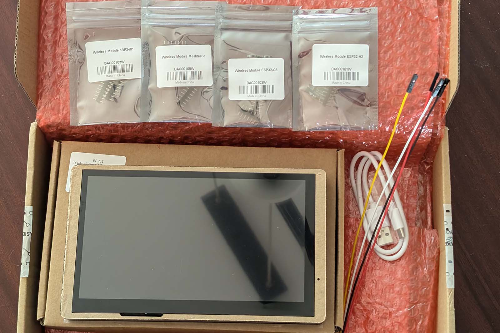
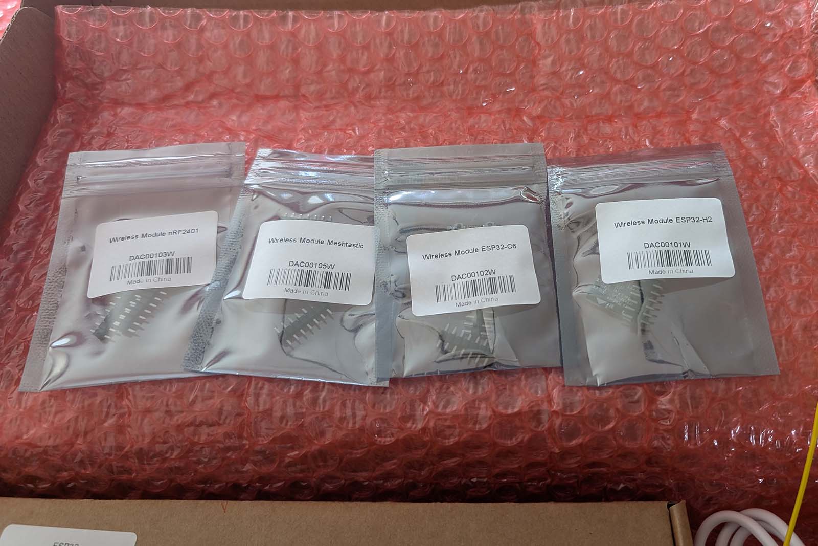
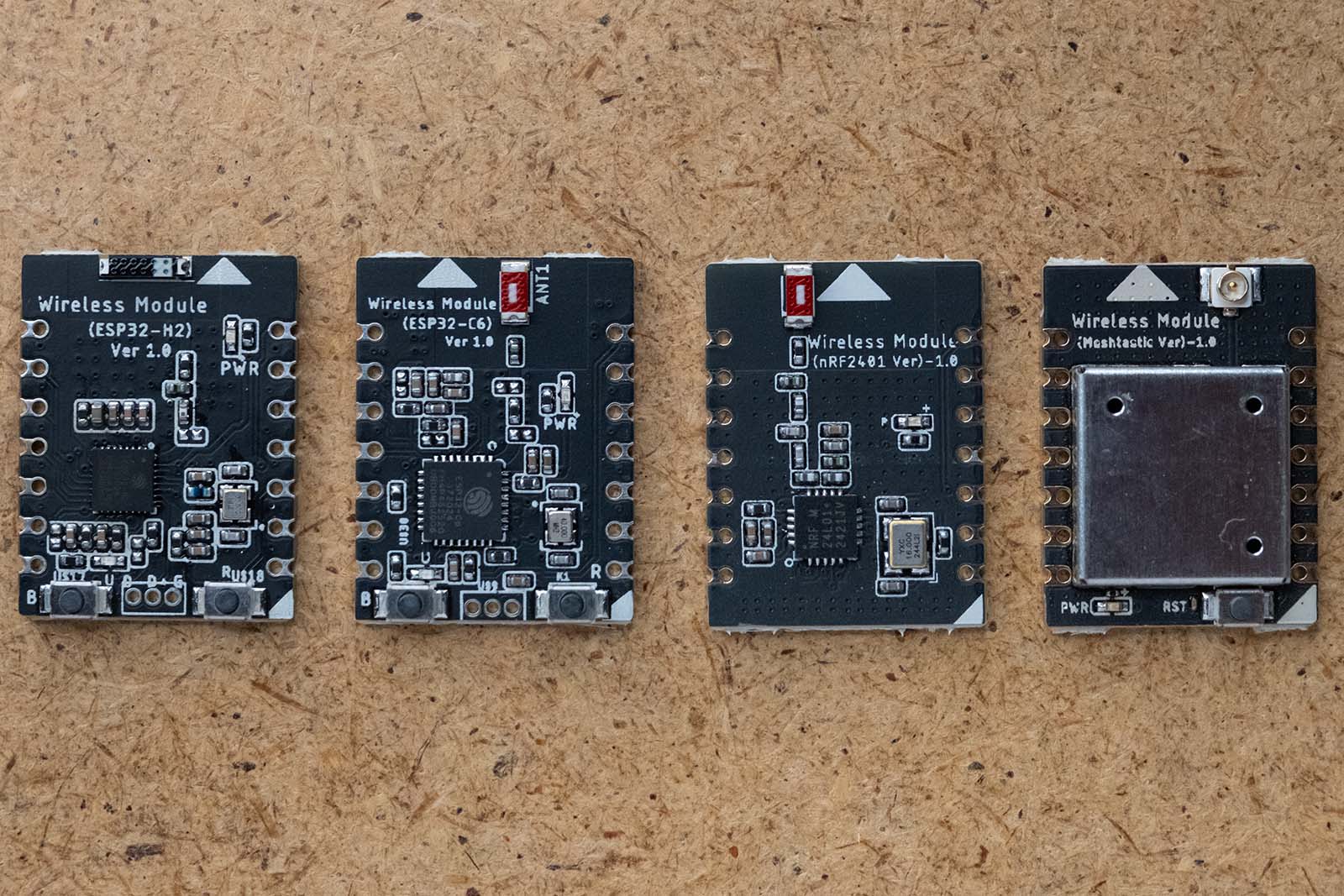
A total of four different expansion modules are also available for the display: the ESP32-H2, the ESP32-C6, the nRF2401 and a LoRa module. Initially, it was still possible to order all modules separately for the display. However, Elecrow has now restructured the range: The display is now sold in two variants. In the first variant, only the ESP32-H2, ESP32-C6 and nRF2401 modules can be ordered as an option, while the second variant is equipped with the LoRa module.
Hardware Setup of the CrowPanel Advance HMI ESP32 AI Display
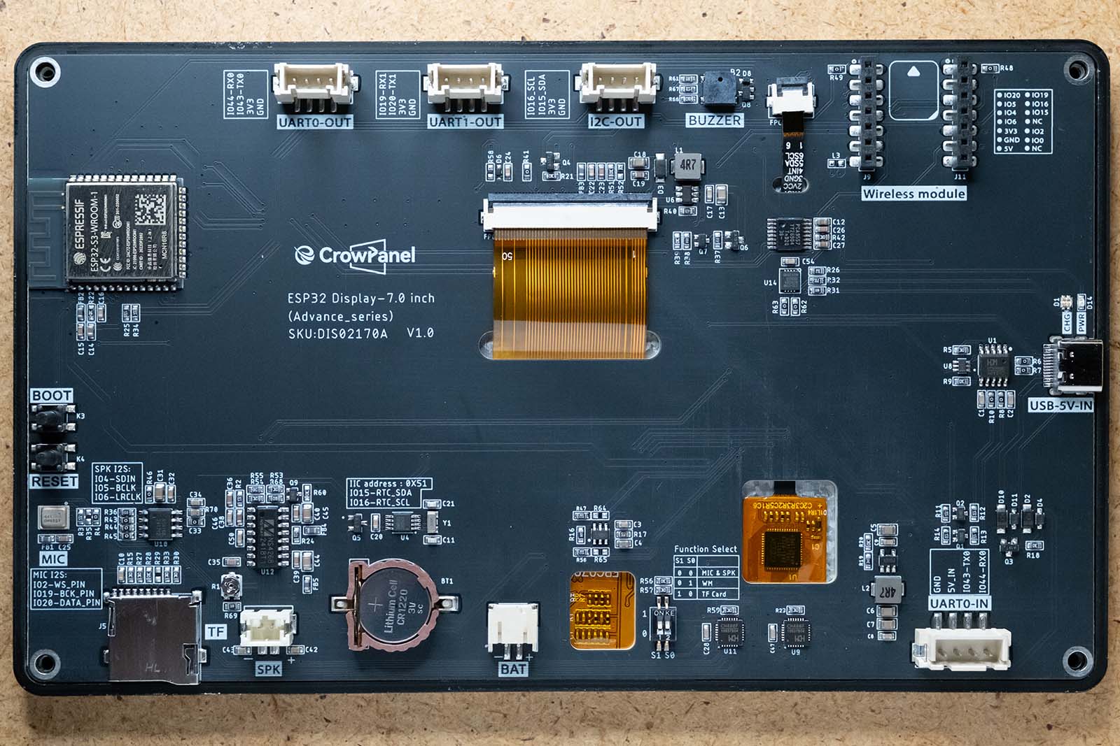
As with all ESP32-based boards with a parallel display, the central component is an ESP32-S3 in the form of an ESP32-S3-WROOM-1-N16R8 module. In addition to 512KB SRAM, 8MB PSRAM and 16MB flash memory, this module has 36 GPIO pins for controlling the peripherals. However, three of these ports are connected to the Octal SPI PSRAM and can therefore not be used for other purposes. The following diagram illustrates how the remaining 33 GPIO pins are connected to the other components of the display.
Most of the pins are required for the parallel display. The display uses the RGB565 format, i.e. 5 bits for red, 6 bits for green and 5 bits for blue. A further 4 lines are used for HSYNC, VSYNC, data enable and the clock signal. This leaves only 13 lines for the rest of the peripherals. Elecrow has therefore resorted to a few tricks that still make it possible to address all external devices, although some compromises had to be made:
-
PCA9557 8-Bit I/O-Expander: The PCA9557 is an 8-bit I/O expander that is controlled via the I2C bus. It is used to expand the number of parallel input/output ports in a system. The module has configuration registers with which each of the 8 I/O pins can be defined as either an input or an output. It also has a register to reverse the polarity of the input signals. These ports are used to control the SHUT and MUTE signals for the amplifier, the reset line of the touch interface and the backlight of the display. The brightness of the backlight is usually controlled via a PWM signal from the LEDC peripherals. With the PCA9557, however, it is not possible to use this PWM signal generator and the I2C bus is not suitable for this task. The display therefore always lights up at full brightness when switched on.
-
CH486F high-speed analog switch: The CH486F is a bidirectional high-speed analogue switch with two independent 4:1 changeover switches. Two of these components are used on the display, each of which switches three GPIO pins. This makes it possible to control all components, but only the component to which the analogue switch is currently set can be used. This setting is made using two DIP switches on the board. The following settings are available for this:
- TF card slot: With this setting, three ports for the SPI interface are used to control an SD card. The CS line of the SD card is connected directly to ground.
- Microphone/amplifier: The two I2S modules of the ESP32-S3 are used here, each of which requires three lines. Elecrow describes the display as “AI-Powered”, which initially suggests that some kind of AI accelerator is installed on the board. However, this is not the case. Rather, it means that it is possible to use the microphone and a speaker to develop a chatbot that uses the API from OpenAI or Google, for example, to process voice input and output the response on the speaker.
- Wireless modules: Four lines for the SPI interface and two lines each for the serial interface and the I2C bus are used for the modules. I will describe the different modules in more detail later.
The remaining GPIO pins are used for the I2C interface, the USB port, the buzzer, the interrupt line of the touch controller and the IO0 pin. In addition, a BM8563 real-time clock and calendar chip is connected via the I2C interface.
In principle, I think it's a very good idea to overcome the limitations of the ESP32-S3 in this way. However, there are some interesting scenarios that cannot be implemented with it. For example, if I use the ESP32-C6 module to control devices via Zigbee or Matter and I want to implement this control via voice commands, then this is not possible. Nor could I store the data from the LoRa module on an SD card. However, I would like to emphasize once again that the problem is not with Elecrow, but with the limited number of GPIO pins of the ESP32-S3, especially when using a parallel display.
The wireless modules
The real highlight of this display are the optional modules. Although some other displays also have a GPIO connector for extensions, only the Elecrow display offers ready-made modules for various wireless technologies that the ESP32-S3 does not support:
- Zigbee: An established standard for home automation and IoT that relies on low-power mesh networks over short to medium distances (primarily 2.4 GHz, also sub-GHz). Ideal for battery-powered sensors, but susceptible to interference in the 2.4 GHz band and with limited range/data rate.
- LoRa: Specialized in extremely long ranges (kilometers) with very low energy consumption (LPWAN) using sub-GHz bands. However, the data rates are very low, which makes it suitable for remote monitoring but not for bandwidth-intensive applications. Gateways are required for network integration via LoRaWAN.
- nRF2401: A cost-effective 2.4 GHz solution popular among makers for short-range communication (up to approx. 100 meters, expandable) with moderate data rates. Easy to use, but susceptible to 2.4 GHz interference and sensitive to power supply.
- Matter: A new standard to standardize smart home devices from different manufacturers. Uses existing technologies such as Wi-Fi and Thread to enable interoperability, easy setup and local control. Relevant for the display via Wi-Fi or optional Thread module.
- Thread: A low-power, secure and reliable IPv6-based mesh network protocol (IEEE 802.15.4 in the 2.4 GHz band) designed specifically for smart home devices and a foundation for Matter. Requires a border router to connect to other IP networks.
- Wi-Fi 6 (802.11ax): The latest generation of Wi-Fi offers significantly higher speeds, capacity and efficiency, especially in environments with many devices. Ideal for data-intensive applications, but with higher energy consumption than low-power technologies.
These options allow the display to be adapted to specific project requirements, from simple short-range communication to complex smart home integrations or sensor networks.
The modules are connected to the display via a 2 x 7 pin GPIO header. The arrangement of the pins is as follows:
This means that three interfaces are available for the modules: UART, I2C and SPI. One small detail is particularly pleasing. The 5 volt power supply is also available. With all the other displays I have used for the weather station so far, I had to solder an extra cable here to supply the fine dust sensor with the necessary voltage.
Elecrow currently offers the following four modules:
ESP32-H2 module
This module is based on the ESP32-H2 chip from Espressif. Its focus is clearly on low-power IoT applications and smart home connectivity..
- Supported protocols: The main strength of the ESP32-H2 is its support for IEEE 802.15.4, enabling Zigbee and Thread communication. This makes it a key component for integrating the display into modern smart home ecosystems, especially for Matter over Thread. It also supports Bluetooth 5 (Low Energy).
- Areas of application: Perfect for controlling smart home devices, setting up sensor networks or participating in Thread/Matter networks.
ESP32-C6 module
The module with the ESP32-C6 chip combines various wireless standards on one chip.
- Supported protocols: Similar to the H2, the C6 also supports IEEE 802.15.4 (Zigbee, Thread) and Bluetooth 5 (LE). The key difference is the additional integration of Wi-Fi 6 (802.11ax) in the 2.4 GHz band. The module also supports the Matter standard (via Wi-Fi or Thread).
- Areas of application: This module is the most versatile option. It is suitable for smart home applications (Zigbee, Thread, Matter), but can also take advantage of the benefits of Wi-Fi 6, such as higher efficiency and better performance in dense wireless environments.
nRF2401 module
This module is based on the well-known nRF24L01+ chip.
- Supported protocols: It is a simple 2.4 GHz transceiver that enables proprietary communication (not Wi-Fi or Bluetooth compatible). It uses the so-called “Enhanced ShockBurst” protocol for reliable transmission.
- Areas of application: Due to its low cost and ease of use (many libraries available for Arduino etc.), it is ideal for low-cost point-to-point or star network connections over short to medium distances (typically up to 100m line of sight, with PA/LNA versions even more). Well suited for remote controls, simple sensor networks or communication between several own devices.
LoRa module
For applications that require communication over long distances with low energy consumption, Elecrow offers a LoRa module based on the Semtech SX1262 chip.
- Supported protocols: Implements LoRa radio technology. Enables communication over several kilometers in the license-free sub-GHz frequency band (e.g. 868 MHz in Europe, 915 MHz in North America). It is intended for use in LoRaWAN networks.
- Areas of application: Ideal for Low Power Wide Area Network (LPWAN) scenarios such as environmental monitoring, smart agriculture, asset tracking or smart city applications where sensor data is sent infrequently and over long distances.
This covers most of the standards that are frequently used in the maker and IoT environment. For more specific requirements, the module slot provides SPI, UART, I2C and both 3.3V and 5V, providing the basis for developing your own modules that are precisely tailored to the requirements of your own project.
CrowPanel Advance: Getting Started with ESP-IDF and LVGL
Elecrow offers some basic information about the display on their wiki. However, there is much more information on their GitHub page, where you can find datasheets, schematics, a SquareLine Studio guide and many code examples for the display, covering both the display and the modules. There are really a lot of examples and I also recommend watching the video tutorials on YouTube.
However, with a few exceptions, all examples are implemented with the Arduino framework. As I prefer the ESP-IDF framework, I have adapted the demo application from my previous article to this display. Basically, the functionality of the CrowPanel Advance display is identical to other parallel displays, but there are some significant differences that make it necessary to adapt the code.
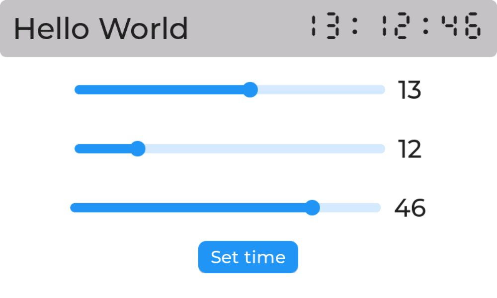
Originally, the brightness of the display could be adjusted in the demo using a slider. However, as this is not possible with this display, the real-time clock can now be set using three sliders instead. In addition, the time is read out in a separate task and shown on the display. The layout of the application was again created in SquareLine Studio and is available on GitHub.
Before exporting the UI data, the paths for Project Export Root and UI Files Export Root must be adjusted. The exported files are then copied to the ui folder of the project. I have tried to cover as many aspects of an ESP32 application as possible with this example:
- Creating the layouts with SquareLine Studio
- Controlling the display and touch controller
- Events in the user interface and corresponding updates to the display
- Changing the display from a task
- Controlling the RTC real-time clock, the IO expander and the buzzer
Large parts of the code are largely identical to the version for the Makerfabs or Sunton display. I will therefore focus on the differences here. First, an overview of the structure of the project.
CMakeLists.txt
platformio.ini                                     Configuration of the project
sdkconfig.defaults                                 Special ESP-IDF settings
boards\crowpanel advance_s3.json                   Configuration of the CrowPanel board
components
components\bm8563                                  RTC driver
components\buzzer                                  Simple driver for the buzzer
components\esp_lcd_touch                           General touch driver code
components\esp_lcd_touch_gt911                     Adapted GT911 driver
components\pca9557                                 Driver for the IO expander
src
src\CMakeLists.txt
src\main.c                                         Main program
src\lv_conf.h                                      LVGL configuration
src\display
src\display\esp32_s3.c                             Display and LVGL initialization
src\display\esp32_s3.h
src\display\elecrow_advanced_7inch_800x480.h       Header file for the CrowPanel board
src\gui
src\gui\gui.h
src\gui\gui.c                                      Functions for changes in the GUI
src\task
src\task\time_task.h                               Simple task that displays the RTC time
src\task\time_task.c
src\ui                                             This folder contains the Squareline Studio export
As described above, Elecrow uses the IO expander to control some of the peripheral pins. The code must therefore be adapted accordingly, as these pins can no longer simply be addressed with gpio_set_direction or gpio_set_level. The basic prerequisite for using the display at all is therefore a driver for the PCA9557 IO expander. I have therefore implemented a simple driver for ESP-IDF that provides the functions to switch the pins on and off or to read them:
/**
 * @brief Initializes the PCA9557 driver.
 *
 * @param bus The I2C bus handle.
 * @param expander_handle Pointer to store the created device handle.
 * @param config Pointer to the I2C device configuration structure (contains device address etc.).
 * @return ESP_OK on success, otherwise an error code.
 */
esp_err_t pca9557_init(i2c_master_bus_handle_t bus, pca9557_handle_t *expander_handle, const i2c_device_config_t *config);

/**
 * @brief Sets the direction of a single pin.
 *
 * @param dev The device handle.
 * @param pin The pin number (0-7).
 * @param direction The direction (PCA9557_INPUT or PCA9557_OUTPUT).
 * @return ESP_OK on success, otherwise an error code.
 */
esp_err_t pca9557_set_direction(pca9557_handle_t dev, uint8_t pin, uint8_t direction);

/**
 * @brief Reads the state of a single pin.
 *
 * @param dev The device handle.
 * @param pin The pin number (0-7).
 * @param value A pointer to store the read state (0 or 1).
 * @return ESP_OK on success, otherwise an error code.
 */
esp_err_t pca9557_read_pin(pca9557_handle_t dev, uint8_t pin, int *value);

/**
 * @brief Writes a state to a single pin.
 *
 * @param dev The device handle.
 * @param pin The pin number (0-7).
 * @param value The state to write (0 or 1).
 * @return ESP_OK on success, otherwise an error code.
 */
esp_err_t pca9557_write_pin(pca9557_handle_t dev, uint8_t pin, int value);

/**
 * @brief Releases the resources of the PCA9557 driver.
 *
 * @param dev The device handle.
 * @return ESP_OK on success, otherwise an error code.
 */
esp_err_t pca9557_delete(pca9557_handle_t dev); // Note: Functionality likely handled by i2c_master_bus_rm_device
The next change concerns the driver for the GT911 touch controller. The reset logic needs to be adjusted here, as the IO expander is also used for the reset line. The adjusted function looks like this:
/* Reset controller */
static esp_err_t touch_gt911_reset(pca9557_handle_t expander_handle, esp_lcd_touch_handle_t tp)
{
    assert(expander_handle != NULL);

    ESP_LOGI(TAG, "Resetting GT911 controller");

    vTaskDelay(pdMS_TO_TICKS(99));  // wait <100ms

    gpio_set_direction(tp->config.int_gpio_num, GPIO_MODE_OUTPUT); // Set Int pin to output
    pca9557_set_direction(expander_handle, 2, PCA9557_OUTPUT); // Set Reset pin to output

    gpio_set_level(tp->config.int_gpio_num, 0); // Set INT pin to 0
    pca9557_write_pin(expander_handle, 2, tp->config.levels.reset);  // Set Reset pin to 0

    vTaskDelay(pdMS_TO_TICKS(11));  // wait >10ms

    pca9557_write_pin(expander_handle, 2, !tp->config.levels.reset);  // Set Reset pin to 1

    vTaskDelay(pdMS_TO_TICKS(6)); // wait >5ms

    gpio_set_direction(tp->config.int_gpio_num, GPIO_MODE_INPUT); // Set Int pin to input

    vTaskDelay(pdMS_TO_TICKS(199)); // wait <200ms

    return ESP_OK;
}
The last important adjustment is configuring the pins and timings of the display. These values can be taken directly from Elecrow's sample programs. The values are entered in the header file elecrow_advanced_7inch_800x480.h.
// Buzzer Configuration
#define BUZZER_GPIO GPIO_NUM_8
#define BUZZER_LEDC_TIMER LEDC_TIMER_1
#define BUZZER_LEDC_CHANNEL LEDC_CHANNEL_1

// I2C
#define I2C_SCL          GPIO_NUM_16
#define I2C_SDA          GPIO_NUM_15
#define I2C_RST          GPIO_NUM_NC
#define I2C_CLK_SPEED_HZ 400000
#define I2C_NUM          I2C_NUM_0

// LCD
#define LCD_PIXEL_CLOCK_HZ     (18 * 1000 * 1000)

#define PIN_NUM_HSYNC          GPIO_NUM_40
#define PIN_NUM_VSYNC          GPIO_NUM_41
#define PIN_NUM_DE             GPIO_NUM_42
#define PIN_NUM_PCLK           GPIO_NUM_39
#define PIN_NUM_DATA0          GPIO_NUM_21   // B0
#define PIN_NUM_DATA1          GPIO_NUM_47   // B1
#define PIN_NUM_DATA2          GPIO_NUM_48   // B2
#define PIN_NUM_DATA3          GPIO_NUM_45   // B3
#define PIN_NUM_DATA4          GPIO_NUM_38   // B4
#define PIN_NUM_DATA5          GPIO_NUM_9    // G0
#define PIN_NUM_DATA6          GPIO_NUM_10   // G1
#define PIN_NUM_DATA7          GPIO_NUM_11   // G2
#define PIN_NUM_DATA8          GPIO_NUM_12   // G3
#define PIN_NUM_DATA9          GPIO_NUM_13   // G4
#define PIN_NUM_DATA10         GPIO_NUM_14   // G5
#define PIN_NUM_DATA11         GPIO_NUM_7    // R0
#define PIN_NUM_DATA12         GPIO_NUM_17   // R1
#define PIN_NUM_DATA13         GPIO_NUM_18   // R2
#define PIN_NUM_DATA14         GPIO_NUM_3    // R3
#define PIN_NUM_DATA15         GPIO_NUM_46   // R4
#define PIN_NUM_DISP_EN        GPIO_NUM_NC

#define HSYNC_BACK_PORCH  8
#define HSYNC_FRONT_PORCH 8
#define HSYNC_PULSE_WIDTH 4
#define VSYNC_BACK_PORCH  8
#define VSYNC_FRONT_PORCH 8
#define VSYNC_PULSE_WIDTH 4

#define LCD_H_RES         800
#define LCD_V_RES         480

// LVGL
#define LVGL_TASK_DELAY_MS   10
#define LVGL_TASK_STACK_SIZE (4 * 1024)
#define LVGL_TASK_PRIORITY   0
With these adjustments, the display can also be used with the ESP-IDF framework. I've also implemented simple drivers for the buzzer and the real-time clock. Unfortunately, I still have a problem with the clock. Reading via the I2C bus doesn't always work. I haven't been able to find the cause yet. Setting disable_ack_check improves the situation, but the time is still not being read correctly. Perhaps someone has an idea what the reason could be?
The code for the demo is available on GitHub.
Unfortunately, the ESP32-H2 and ESP32-C6 modules from my batch have a problem: They were delivered without pre-installed firmware, and the necessary flashing via an external serial programmer is complicated by very short header pins. According to Elecrow, commissioning this specific batch currently requires temporarily soldering pin headers. However, this problem has been resolved in newer production batches. I will therefore describe how to use the modules in a second part.
Conclusion
My overall conclusion about the Elecrow CrowPanel Advance 7" is very positive. Elecrow delivers a powerful package with a good 7-inch IPS touch display, the ESP32-S3, useful extras such as a real-time clock with battery backup, audio input/output, and, above all, the flexible concept of the optional wireless modules. It thus provides an excellent basis for sophisticated outputs.
The hardware designers faced the challenge of accommodating the wealth of peripherals despite the limited GPIO pins of the ESP32-S3 when controlling a parallel display. The chosen solutions using I/O expanders and analog switches are clever, but lead to understandable compromises: The limitation that the SD card, audio peripherals, and wireless modules cannot be active simultaneously, but must be selected via DIP switches, is understandable given the circumstances.
The crucial weakness, however, is the lack of PWM control of the backlight. This limitation unfortunately makes it unsuitable for use in my weather station. The solution would actually be quite simple: An active instead of passive buzzer, controlled via a line from the IO expander, and the freed-up GPIO pin would be used for the PWM signal.
Apart from this specific shortcoming, which is only relevant for certain use cases, the CrowPanel Advance 7" is an extremely interesting and versatile platform with a unique modular approach. Anyone looking for a large ESP32 display with maximum flexibility in wireless standards and who can do without variable brightness will find this a strong option for many exciting projects.