Controlling a Bodet Flip-Display Slave Clock with the ESP32
I have to admit, after my last article about the Siemens clock, I've become a bit obsessed with slave clocks. Shortly after, I snagged four more clocks on a classifieds platform. This time, however, the clocks don't have hands, but they are beautiful flip-clocks. These clocks were manufactured in the late 1970s by the company Bodet and were often distributed by other companies such as Siemens or TN.
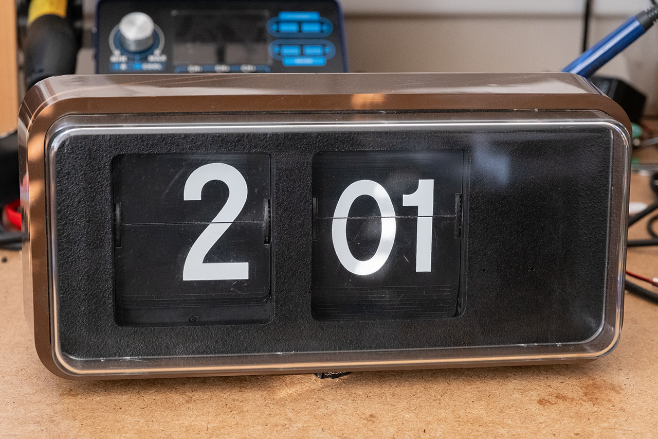
The special thing about these flip-clocks is their size. The principle of flip-clocks is mainly known from old radio alarm clocks, where the display is only a few centimetres in size. These clocks, on the other hand, are over 30 cm wide and 15 cm high, making them a real eye-catcher. Prices of up to 500 euros are sometimes asked for these clocks on various sales platforms. Fortunately, all four clocks together cost me considerably less, so I had to buy them, especially as they are all in extremely good condition. Only the front of the clocks was a little scratched.
As you can see from the photos, these flip-clocks come in different colours and the front cover also has different shapes. My impression is that the domed version is the older shape.
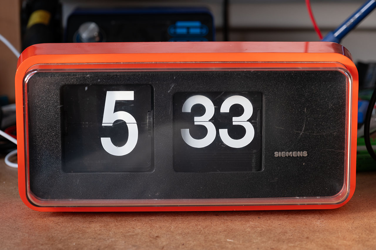
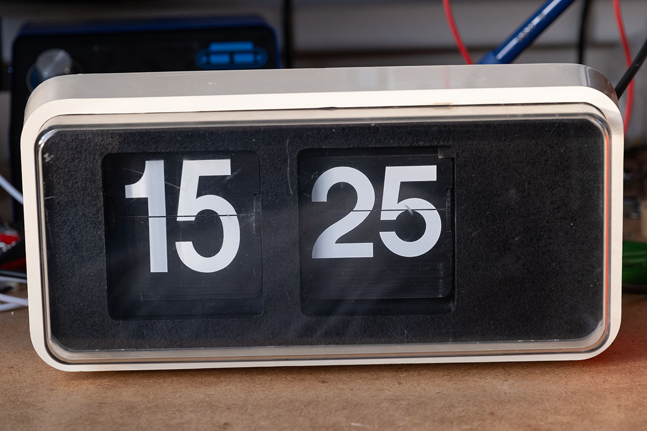
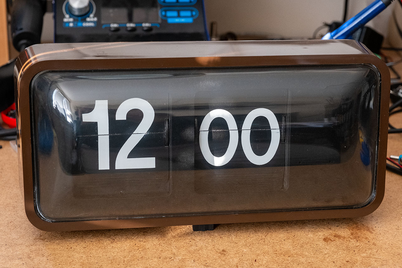
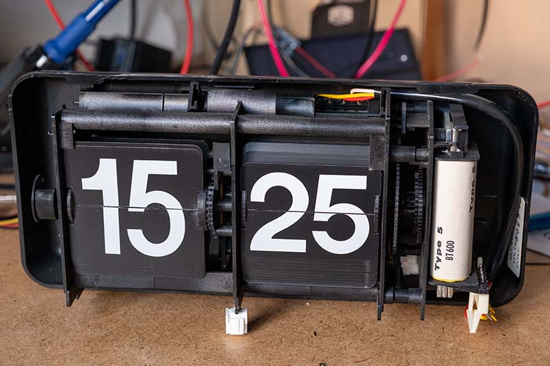
There are other colors such as blue or yellow, but unfortunately I have not yet been able to find any suppliers where you can buy them at a reasonable price. There are also slight differences in the internal construction of the clocks. One model has metal struts that are screwed together with nuts, while other models are made entirely of plastic.
Controlling the slave clock
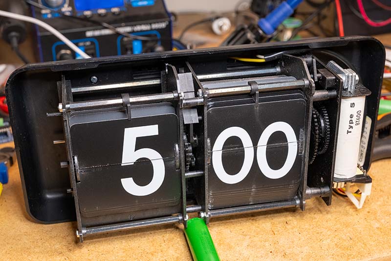
As mentioned above, these clocks are slave clocks, which means that an external controller is required to operate them. I have already explained the basic principle of slave clocks in my article on the Siemens clock. This principle also applies to this flip-clock, with the difference that the hands are not moved here, but the split-flaps are. The clock receives a pulse every minute, which drives the minute display. The internal mechanism of the slave clock moves the hour display every hour (quite loudly).
For the control system, I mainly use the same components that I already used for the Siemens slave clock:
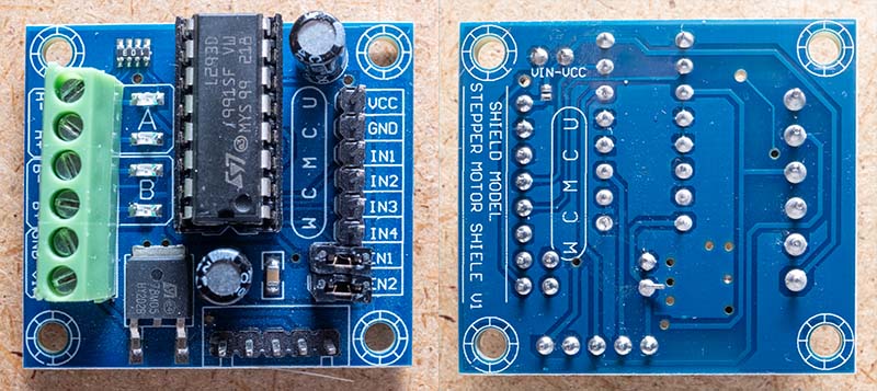
L293D motor driver
The L293D is a 4-fold half-H bridge driver for controlling motors, relays and solenoids. It enables bidirectional control of up to two motors or one-sided operation of four motors with 600 mA per channel. Each output pin pair forms a complete H-bridge, with control via separate enable pins. Two half-H drivers are combined to form an H-bridge for directional control of one motor.
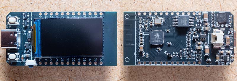
LILYGO T-Display ESP32 Microcontroller
The LILYGO T-Display is a compact ESP32 development board with an integrated 1.14-inch display (ST7789, 135x240 pixels). It offers Wi-Fi connectivity, two freely usable buttons and a 5V voltage regulator integrated on the board. Thanks to the support of the TFT_eSPI library, the display is easy to control. Inexpensive clones with 16 MB QSPI flash are available on AliExpress for less than 7 euros.
Stromversorgung
I found a cheap step-up converter on AliExpress that can be operated via USB-C and has an adjustable output voltage of 4.3 - 27 volts. This allows you to operate both 12 volt and 24 volt slave clocks. There is also a charge controller for 18650 Li-Ion batteries on the board. This means that the controller can also bridge power failures.

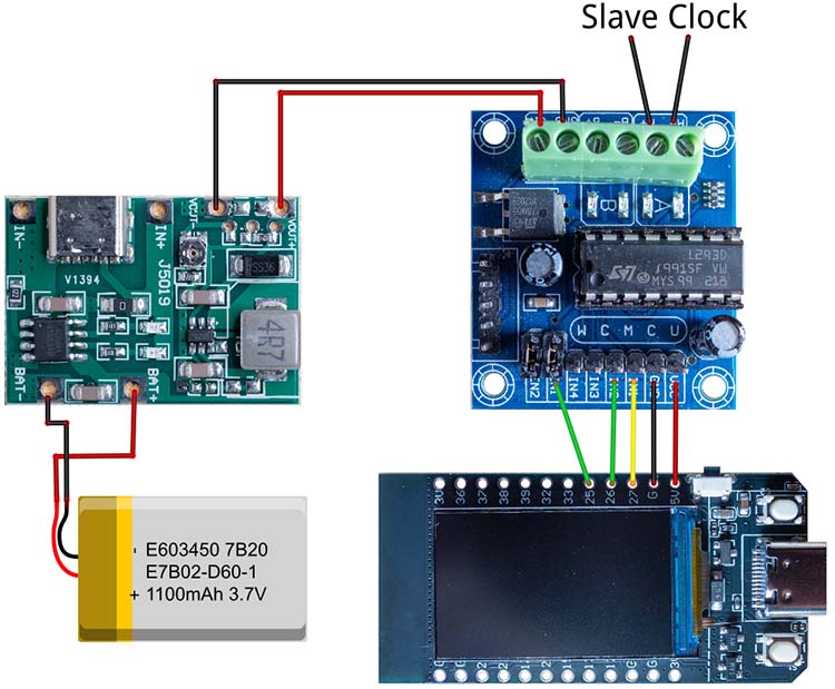
The circuit
Now all that remains is to wire the three circuit boards together. The following picture shows how the individual pins must be connected:
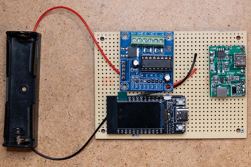
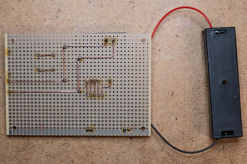
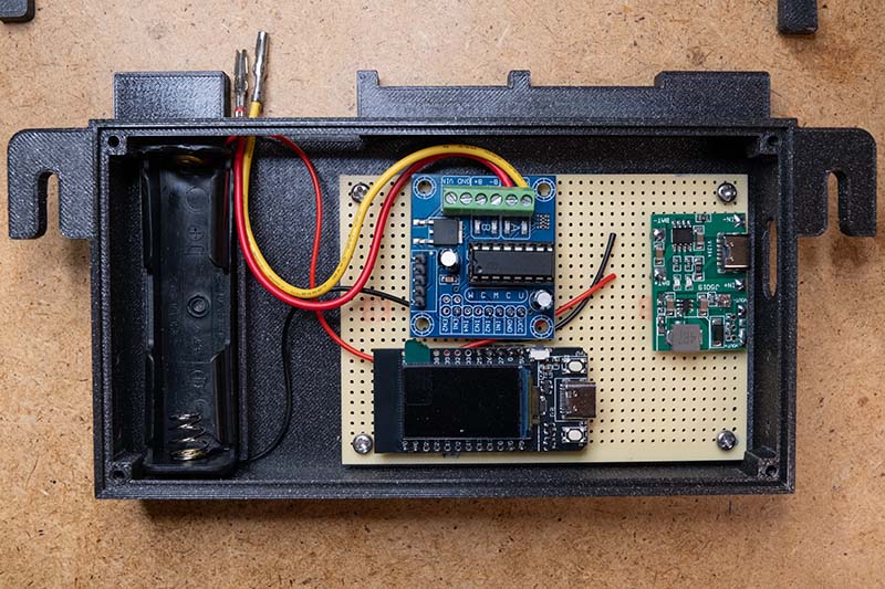
As this circuit is very simple, I simply soldered the three boards onto a breadboard and connected the corresponding pins on the underside with copper wire. I desoldered the connector strip of the L293D board first and then soldered the necessary pins back on the underside. The jumper for the enable input must be removed, as the microcontroller is supposed to control when the motor receives power. The entire structure of the slave clock control then looks like this:
The wiring of the stepper motor
The stepper motor in this slave clock can be operated with 12 or 24 volts. As I am using a 12-volt control unit, the contacts must be connected as shown in the following picture:
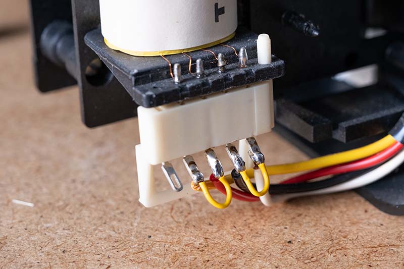
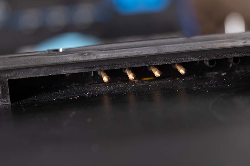
The four connections from the coil are led to the outside of the clock via cables to the case. The following picture shows the pins on the back of the clock.
Here you can see the four pins from close up. Normally, this clock also comes with a suspension bracket that can be screwed to the wall. There is a corresponding plug in this suspension into which the pins engage when the clock is hung up.
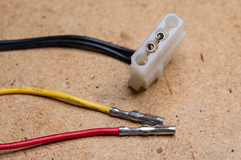
Unfortunately, this suspension was not included with my clocks. I therefore had to look for another solution for connecting the control unit to the pins. After a lot of trial and error, I finally found a good solution. The socket contacts in the 4-pin Molex plugs from old PCs fit the pins perfectly and fortunately I still have a few of them in my stash.
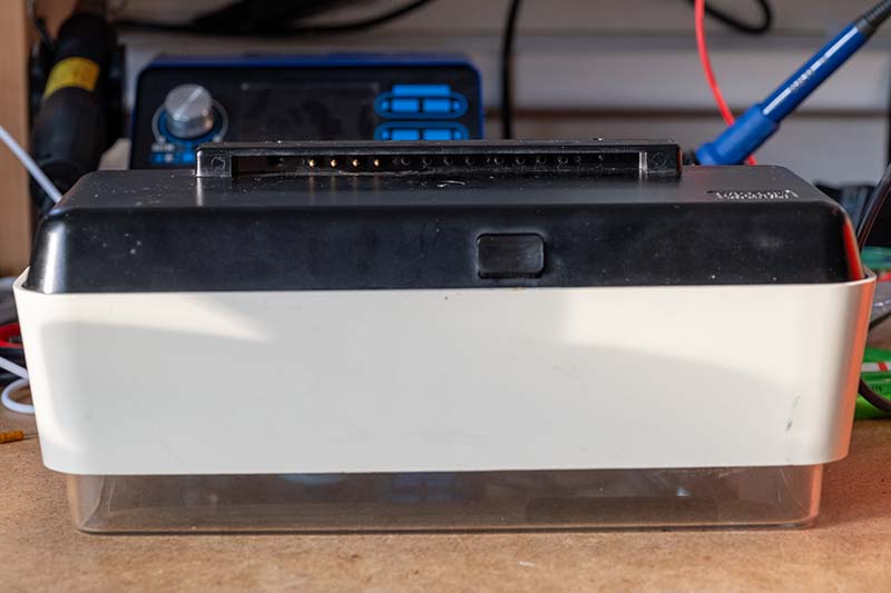
The case
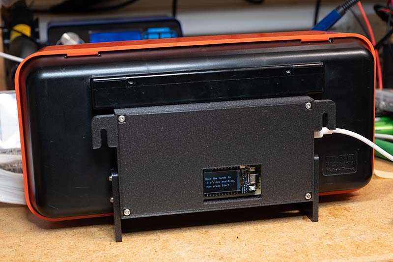
Of course, the electronics also need to be placed in a case that is as inconspicuous as possible. It should be possible to hang the clock on the wall or simply place it on a shelf. The result looks like this:
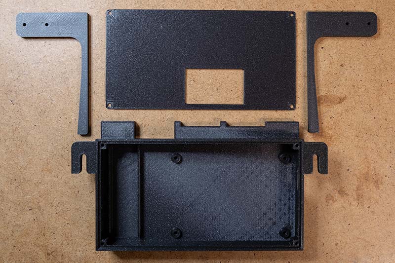
The side feet are only required if the slave clock is to stand on a shelf. They are slightly slanted so that the clock stands completely straight, as the clock housing does not form a 90° angle.
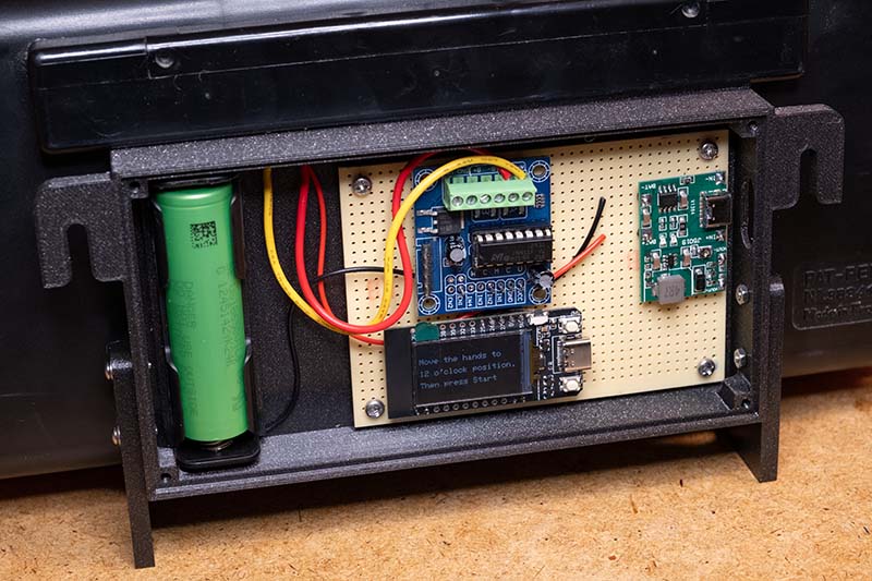
The holder for the battery is simply glued into the provided gap, the rest is screwed on. The connections are simply fed through a cut-out in the case and plugged into the pins on the watch.
The controller software
As the hardware for controlling the slave clock is identical to the Siemens clock and the principle of control has not changed, I was able to use the software directly. I only added a constant to it to define whether it is a 12 or 24 hour clock. This is not so important for operation, but at least it makes a small difference when setting the clock. I have also added the SmartConfig library so that you don't have to store the Wi-Fi credentials in the code.
The controller software was developed in Visual Studio Code with the PlatformIO extension. Arduino is used as the framework, since the TFT_eSPI graphics library requires this. The software can be divided into two main areas: setup mode and operation mode.
Setup mode
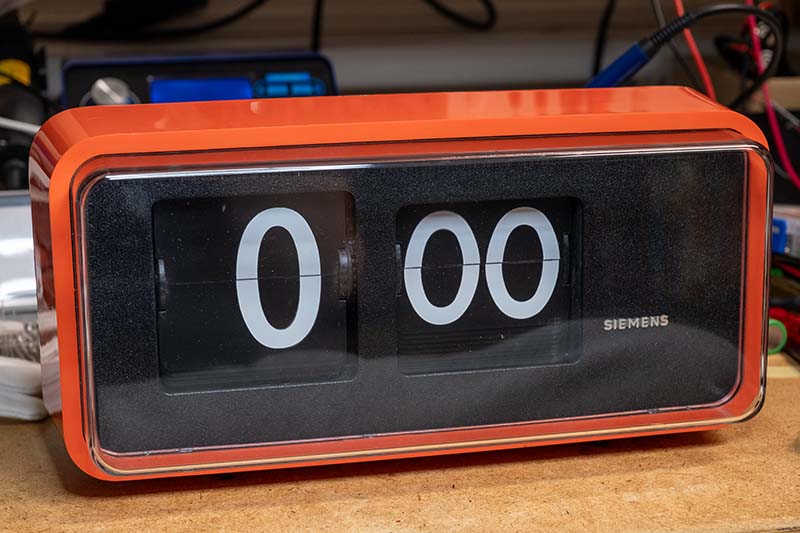
In setup mode, the digits of the flip-clock are adjusted manually to bring them to the 0:00 position. This is necessary to synchronise the clock with the actual time. The first button (BUTTON_MOVE_PIN, GPIO_NUM_0) is used to move the digits forwards by the minute. A short click advances by one minute, while a longer press advances the digits continuously. The ButtonHandler class controls the buttons.
Operation mode
As soon as the digits are set to 0:00, the second button (BUTTON_START_PIN, GPIO_NUM_35) is pressed to switch to operation mode. In this mode, the ESP32 connects to the Wi-Fi , synchronises the time via an SNTP server and starts two tasks:.
Wi-Fi connection: The WifiSmartConfig class takes over the management of the Wi-Fi connection. Firstly, an attempt is made to connect using saved Wi-Fi access data. If this fails, SmartConfig mode is started to receive the access data via an app
SNTP synchronisation: After a successful Wi-Fi connection, the time is synchronised via the SNTP server. The initSNTP function of the WifiSmartConfig class initialises the SNTP client and defines a callback that is called as soon as the time is synchronised:
Move Task: This thread is responsible for moving the digits. It continuously compares the actual position of the digits with the target position every minute and calculates the difference. The digits are then rotated by this difference
Display task: This thread shows the current time and the connection status on the display. The connection status is shown by coloured rectangles: Red for no Wi-Fi connection, orange for Wi-Fi connection without time synchronisation and green for successful time synchronisation.
Basically, the software is designed in such a way that it should work for all slave clocks if the L293D is used as the driver. The slave clock control software is available on GitHub.
Conclusion
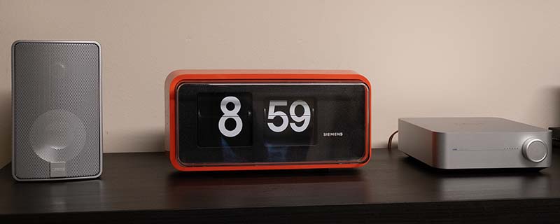
These large flip-clocks are a real eye-catcher and don't look a bit outdated despite their age. I thought long and hard about which of the four clocks I would keep because, unfortunately, I like them all. In the end, I decided on the red model. I will probably give the others away to friends
I treated the front cover with a polishing paste and now there are virtually no scratches to be seen.
This beautiful clock now decorates my office. However, I should probably slowly realize that I now have enough clocks in my apartment. I don't know why these old clocks fascinate me so much. Maybe it's the timeless design or simply the fact that the technology from back then still works perfectly 50 years later.
If you have any questions or other suggestions, just send me a message. I'm always happy to receive feedback!