ESP32-based control of slave clocks with the L293D H-bridge driver
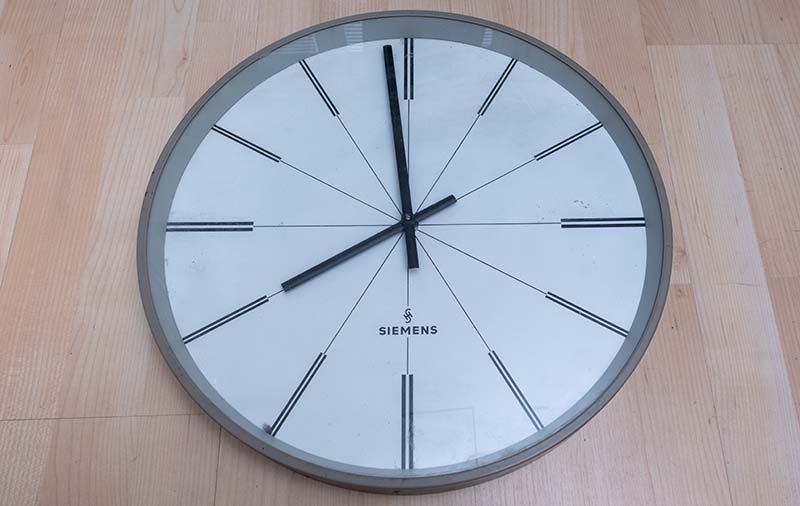
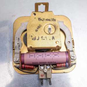
A few weeks ago, I acquired a beautiful slave clock from Siemens quite cheaply. With a diameter of 42 cm and a simple and timeless design, this clock has lost none of its charm even after all these years and inspires me every time I look at it.
In the meantime, I have developed and successfully implemented a suitable control system so that the clock is now fully functional again. In this article, I would like to present the control system I have developed, which makes it possible to operate the clock without an expensive master clock.
Slave clocks
In the past, slave clocks were an essential part of buildings such as railroad stations, factories or schools. They were controlled centrally via a master clock, which sent a signal to the slave clocks to keep them synchronized. This meant that all the clocks in the building always displayed the same time.
Technically, many slave clocks are characterized by their simple but robust mechanics. A central component is often the Lavet stepper motor, which converts electrical impulses into rotating movements. The control signal for the slave clock changes polarity with each pulse. This reversal of polarity ensures that the coil in the Lavet stepper motor is alternately magnetized and the rotor is pulled into a new position. In this way, the rotor turns in regular steps, which moves the clock hands forward step by step - usually in minute increments.
The Siemens clock
As mentioned above, the side clock has a diameter of 42 cm, which makes it just about suitable for my living room. It would probably look even better in larger or higher rooms in an old building. Unfortunately, I don't have any precise information about how old the clock is. However, based on the design and construction, it could date from the 1950s or 1960s.
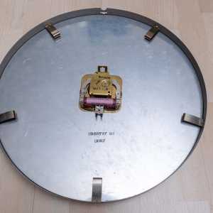
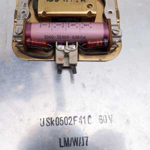
Most slave clocks are designed for operating voltages of 12, 24 or 60 volts, with 24 volts being used particularly frequently. The Siemens clock is originally designed for 60 volts, but a voltage of 12, 24 or 48 volts can also be used by bridging the series resistors.
The control system
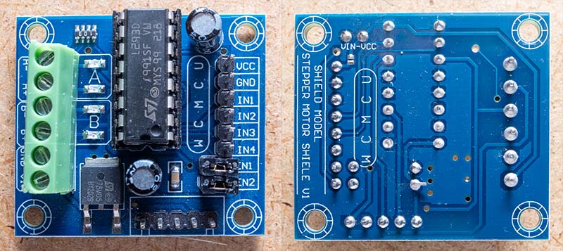
To operate a slave clock, all you have to do is switch the polarity of a suitable voltage every minute. After a short search, you will quickly come across the use of an H-bridge, as it is ideal for simply changing the polarity. You can either build this H-bridge from individual components or simply use a ready-made bridge driver. I opted for the L293D motor driver, as there are inexpensive modules that come with a voltage regulator as well as the motor driver. This voltage regulator is very useful for the second component, the microcontroller. The microcontroller takes care of the time synchronization and sends the necessary control signals to the L293D. I also use a third component for my control system, namely a battery charger with a step-up converter. This means that the clock continues to run even in the event of a power failure and can be operated with a standard USB-C power supply unit. Here are the individual components in detail:
The L293D motor driver
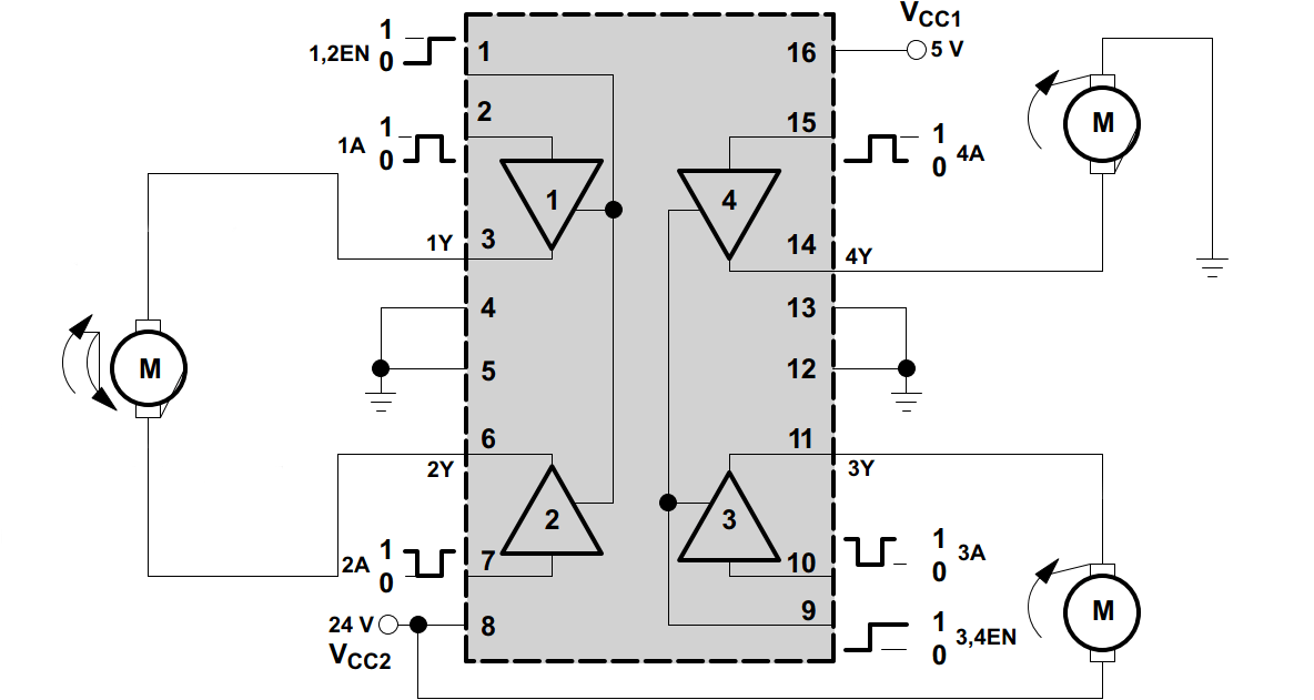
The L293D is a 4-way half-H bridge driver designed for driving inductive loads such as motors, relays and solenoids. It offers bidirectional control for up to 600 mA per channel. This means that two motors can be controlled simultaneously in both directions (forward and reverse) or four motors in one direction.
Each output pin pair (1Y/2Y and 3Y/4Y) corresponds to a complete H-bridge driver. There is an enable pin (1,2EN and 3,4EN) for each of these drivers. To control a motor in both directions, two of the half-H drivers are combined to form an H-bridge.
The L293D is characterized by the following features:
- Wide supply voltage range: The L293D can be operated with a supply voltage of 4.5 V to 36 V. There are separate connections for the logic supply (VCC1) and the motor supply (VCC2). Due to the upper limit of 36 V, only slave clocks with 12 or 24 V can be operated.
- Integrated freewheeling diodes: The L293D has integrated freewheeling diodes that protect the drivers from voltage peaks that occur when inductive loads are switched off.
- TTL-compatible inputs: The inputs of the L293D are compatible with transistor-transistor logic (TTL) and can tolerate up to 7 V, and also work with the 3.3 V of the ESP32.
- High peak current: Each driver can handle peak currents of up to 1.2 A for short periods.
- Thermal protection: The L293D has integrated thermal protection that shuts down the chip in the event of overheating..
The module also contains a linear voltage regulator of type 78M05, which can supply a maximum of 500 mA. This supplies both the L293D and the microcontroller with the required 5 volts, which simplifies the entire control system somewhat, as only one power supply is required for the motor and electronics.
Of course, the data sheet of the L293D does not mention slave clocks. Nevertheless, it is ideally suited for controlling a slave clock, as it provides the necessary H-bridge and can be controlled by the microcontroller with just a few control signals.
The ESP32 microcontroller
The requirements for the microcontroller are not particularly high for this project. I have considered the following points:
- Wi-Fi to synchronize the time
- Two buttons to set the clock to a start position and to start normal operation
- Display to show the current time and Wi-Fi status
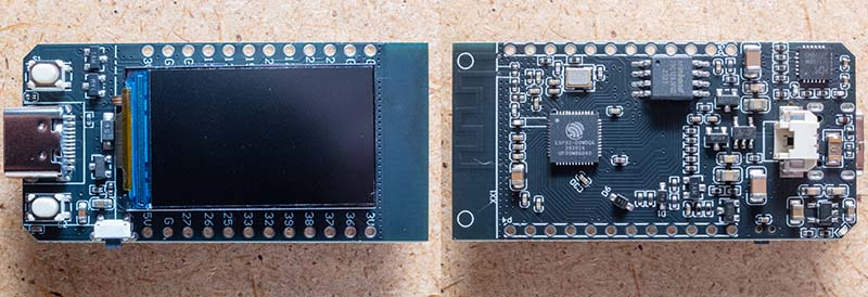
After a short search, I came across the LILYGO T-Display. This board completely fulfills all my requirements:
- ESP32, so Wi-Fi is available
- 1.14 inch display with ST7789 driver
- Resolution: 135 x 240 pixels
- Voltage regulator for 5 volts is on the board
- Two freely usable buttons
- The TFT_eSPI graphics library supports this board
There are also clones of this board on AliExpress. I got my board there for less than 7 euros, which even has 16 MB QSPI flash.
In principle, any other ESP32 board would also work. Instead of the display, you could use an RGB LED, for example, and the time on the display is just a gimmick anyway. Alternatively, it would also be possible to run a small HTTP server on the ESP32 and implement the control with a web interface.
Optional: Battery supply in the case of power failure
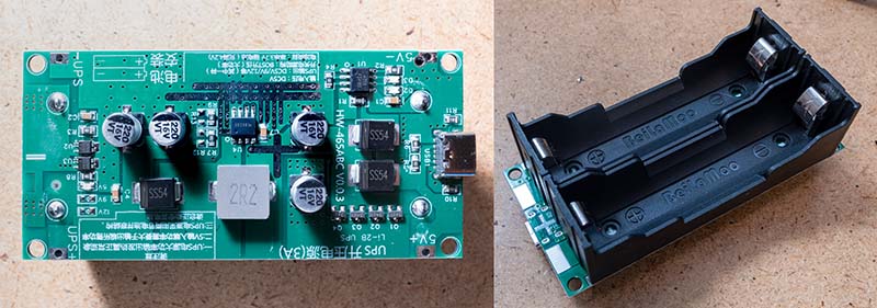
Basically, the controller would be ready. With a 12 or 24 volt power supply connected to the L293D board, the clock would run like this. However, in the event of a power failure, the clock would have to be reset. I have therefore installed an additional module that has several useful features:
- The power connection is a standard USB-C plug. This means that any USB-C power supply can be used.
- A step-up converter converts the 5 volts into 12 volts. I therefore operate my slave clock with 12 volts. Unfortunately, I have not been able to find a corresponding circuit board for 24 volts.
- A charge controller charges two 18650 Li-Ion batteries. In the event of a power failure, these batteries supply the step-up converter.
The power of this circuit board is somewhat oversized for the operation of the clock (it supplies up to 15 watts), but as you can get the part from AliExpress for less than 3 euros, I don't mind. I desoldered the battery holders because otherwise the circuit board wouldn't fit behind the clock. Instead, I connected a different holder for an 18650 Li-Ion battery.
The complete control system
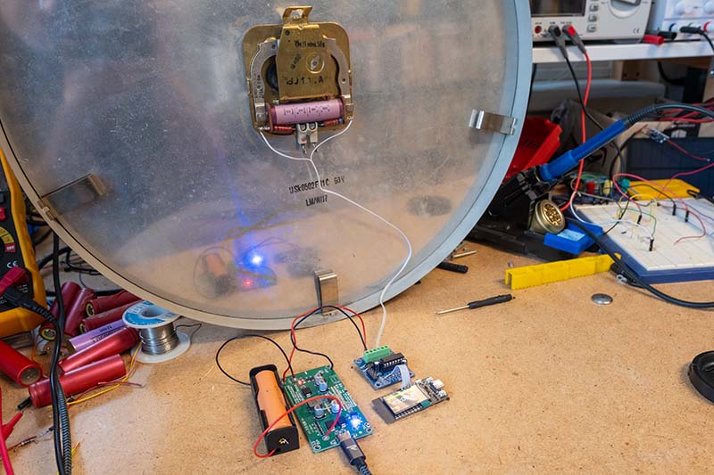
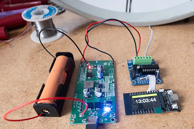
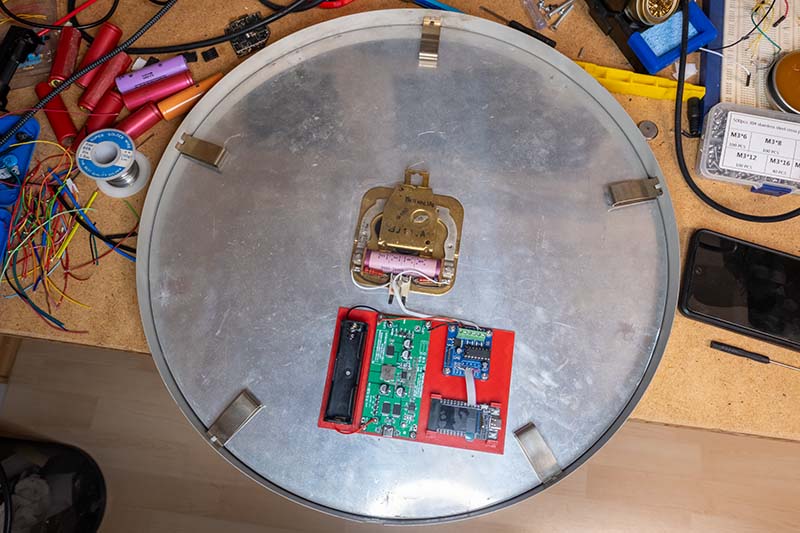
Since not many connections between the individual boards are necessary, the structure looks quite tidy. The first prototype of the controller looks like this:
The pins of the ESP32 board and the L293D happen to be almost exactly opposite each other and can therefore be easily connected with a short piece of ribbon cable. I soldered the connector strip to this. The jumper for the enable input (1,2E) must be removed, as the microcontroller should control when the motor receives power.
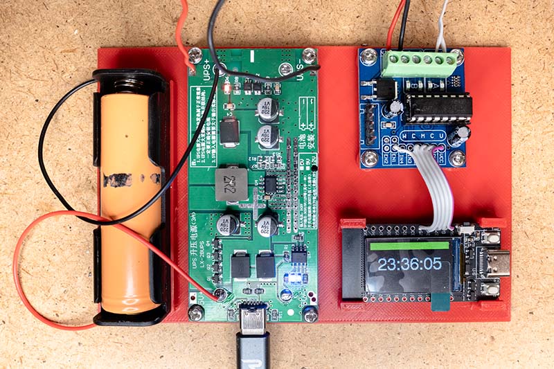
To build the components into the clock, I designed a simple holder and printed it out with the 3D printer.
I could perhaps have packed the parts on the holder a little tighter. But it fits into the clock without any problems. I simply glued the holder to the clock with a few drops of glue.
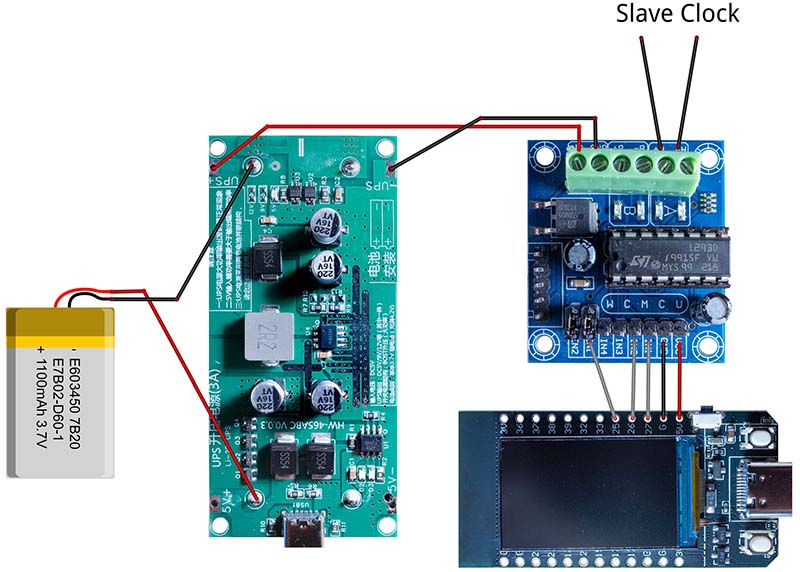
That completes the hardware. Here is a picture of how the three boards are wired:
With this setup, all slave clocks that work with 12 or 24 volts can be controlled without any problems. I also use this circuit to operate my Bodet Flip-Display slave clocks.
The control software
The controller software is developed in Visual Studio Code with the PlatformIO extension. The TFT_eSPI graphics library requires the Arduino framework, so I used this framework. You could possibly also use LVGL, but that seems a bit oversized to me here.
I start with the platform.ini file, which is used to configure the project and integrate the required graphics library. Apparently there are always problems with how the TFT_eSPI library is used with this board. The following file configures the dependency to TFT_eSPI in the current version 2.5.43 and defines all necessary parameters. No changes need to be made in TFT_eSPI itself.
[env:lilygo-t-display]
platform = espressif32@6.9.0
board = lilygo-t-display
framework = arduino

monitor_speed = 115200
monitor_raw = yes

;upload_speed = 921600

build_unflags =
    -std=gnu++11
build_flags =
    -std=gnu++17
    -DCORE_DEBUG_LEVEL=3
    -DUSER_SETUP_LOADED=1
    -DST7789_DRIVER=1
    -DTFT_SDA_READ
    -DCGRAM_OFFSET
    -DTFT_WIDTH=135
    -DTFT_HEIGHT=240
    -DTFT_MISO=-1
    -DTFT_MOSI=19
    -DTFT_SCLK=18
    -DTFT_CS=5
    -DTFT_DC=16
    -DTFT_RST=23
    -DTFT_BL=4
    -DTFT_BACKLIGHT_ON=HIGH
    -DLOAD_GLCD
    -DLOAD_FONT2
    -DLOAD_FONT4
    -DLOAD_FONT6
    -DLOAD_FONT7
    -DLOAD_FONT8
    -DLOAD_GFXFF
    -DSMOOTH_FONT
    -DSPI_FREQUENCY=40000000
    -DSPI_READ_FREQUENCY=6000000
    -DCONFIG_IDF_TARGET_ESP32

board_build.flash_size = 16MB


lib_deps =
    bodmer/TFT_eSPI@^2.5.43
The software is generally divided into two parts. Firstly, the controller is in setup mode. Here, one button is used to move the hands forward by the minute. A short click advances one minute, a longer press moves the hands faster. The hands must be turned to the 0:00 position. Then press the second button. This starts the normal time mode. First, the ESP32 connects to the Wi-Fi and then waits until the time has been synchronized with the SNTP server. Two threads are then started. The first thread continuously compares the actual position of the hands with the target position and calculates the difference. The hands are then rotated by this difference. The second thread shows the current time of the ESP32 and the current connection status on the display:
- Red: No Wi-Fi connection
- Orange: Wi-Fi connection available, but no time synchronization yet
- Green: The time could be set via SNTP
At the moment, the WLAN access data and the time zone are still stored as variables in the code. I may try to read out the access data via SmartConfig later.
The following diagram shows the timing of the signals sent to the L293D.
I determined the length of the enable signal 1.2E by trial and error. From a value of 350 milliseconds, the hands continue to turn reliably. At lower values, there were occasional dropouts. 1A and 2A are always inverse to each other and determine the direction of rotation of the Lavet stepper motor. The direction of rotation must be changed with each step so that the hands continue to move. This means that although the stepper motor in the clock moves in both directions, the hands only ever turn in one direction. Consequently, the clock cannot be adjusted backwards if you want to set the correct time. The following video shows this process:
The software for the slave clock control is available on GitHub.
Conclusion
I am really absolutely fascinated by this clock. It is an absolute eye-catcher in my home! And I've learned a lot again. Now I know how slave clocks work and what an H-bridge is. Of course, I could have made things easier for myself by simply buying a new clockwork. But I have doubts as to whether such a clockwork has the necessary torque for the large metal hands. Besides, these hands won't fit on a new movement without a modification.
If you have any questions or tips, please leave me a message - I look forward to your feedback! Have you ever converted a slave clock yourself or implemented a similar project?
